
Multi-functional bionic corn thresher

A thresher, multi-functional technology, applied in threshing equipment, agricultural machinery and implements, applications, etc., can solve the problems of reducing the broken rate of corn kernels, low work efficiency, single function and other problems, and achieve strong pecking ability. The effect of reducing corn damage and reducing the rate of grain breakage

Inactive Publication Date: 2012-03-14
HENAN UNIV OF SCI & TECH
View PDF5 Cites 13 Cited by
  • Summary
  • Abstract
  • Description
  • Claims
  • Application Information

AI Technical Summary

Problems solved by technology

The rotation speed of the drum is above 700r / min, and the outer edge of the drum directly acts on the corn kernels at a linear speed greater than 8m / s, and threshing is achieved by high-speed beating, but during the beating process, the nail teeth on the drum or the beating Gluten is very harmful to corn kernels, so this kind of corn kernels can only be used in flour, feed processing, etc.
At present, there is also a differential-speed corn thresher. The drum speed of this thresher is relatively slow. When threshing corn ears, it has a low corn kernel breakage rate and a high cleaning rate. Corn kernels are often used in storage, transportation, and seed processing. In terms of processing, this differential thresher does not reduce the crushing rate of corn kernels very much, and its drum rotates slowly, resulting in low work efficiency
[0004] According to the above, the existing corn threshers mainly have the following deficiencies: (1) During the threshing process of corn ears, the threshing damage rate of corn kernels has not been eliminated or greatly reduced; (2) The function is single, and each The thresher can only perform one form of threshing of corn ears, such as threshing with high grain breakage rate and high threshing efficiency, which is used in flour and feed processing; while threshing with low grain breakage rate and high cleaning rate is used For storage, transportation, seed processing, etc.

Method used


Image

  • Multi-functional bionic corn thresher
  • Multi-functional bionic corn thresher
  • Multi-functional bionic corn thresher

Examples


Embodiment Construction

[0023] The present invention will be further described below in conjunction with the accompanying drawings and embodiments.

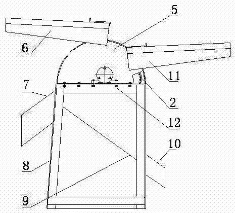
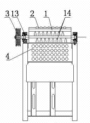
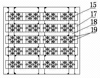
[0024] like Figure 1-6 As shown, a multifunctional bionic corn thresher comprises a frame, a threshing drum 1, a threshing screen 2, a belt pulley 3 connected with the threshing drum 1 and a sieve plate 4, and the frame is composed of a matching upper shell 5 and the lower frame 8, and the upper casing 5 and the lower frame 8 are fixedly connected by bolts 12, the upper casing 5 is provided with a first feeding port 6 and a second feeding port 11, and the lower frame 8 is provided with There are corncob outlet 7 and grain outlet 10, the two ends of the threshing cylinder 2 are movably installed in the upper casing 5 through bearings 13, and the outer circumferential surface of the threshing cylinder 2 is evenly provided with a plurality of beak-shaped grain levers 14, so that The threshing screen 2 is arranged on the side of the threshing drum 1, and ...


PUM


Abstract

The invention discloses a multi-functional bionic corn thresher which comprises a rack, a threshing cylinder, a threshing sieve, a sieve plate and a belt pulley, wherein the belt pulley is connected with the threshing cylinder; the rack is composed of an upper shell and a lower frame which are matched, and the upper shell is provided with a first feed inlet and a second feed inlet; the axial circumferential surface of the threshing cylinder is provided with a chicken beak-shaped kernel driving lever; and the threshing sieve is provided with a chicken beak-shaped threshing lever. The corn thresher disclosed by the invention can satisfy the threshing needs of corn kernels with different uses; and according to the principle of bionics, a threshing unit (such as teeth or striking ribs) on the cylinder is designed into the shape of a wedge-shaped beak part of a chicken, so that an effect of loosing clusters and then threshing the clusters can be achieved, thereby greatly reducing the damages on corn kernels during threshing.

Description

technical field [0001] The invention belongs to the field of agricultural machinery, in particular to a multifunctional bionic corn thresher used for corn thresher. Background technique [0002] Corn is not only one of the three major food crops in my country and the world. Corn threshing is a key link in harvesting work. It determines the degree of damage to corn kernels. The storage period of corn kernels will be affected by the degree of damage to the kernels. The seeds have a low germination rate, are prone to mold, insects, and are easily broken, and reduce their market value and export value. [0003] The existing drum-type corn threshing machine uses the principle of high-speed impact to threshing corn. The threshing drum is the core component of the threshing machine. During the threshing process, the threshing drum rotates at high speed. Strikes are applied to the ear of corn to separate the kernels from the cob. The rotation speed of the drum is above 700r / min, an...

Claims


Application Information

Patent Timeline
IPC IPC(8): A01F11/06
Inventor 李心平马福丽李玉柱王显辉周伟鲁春胜王涛
Owner HENAN UNIV OF SCI & TECH
Learn More