Elevator energy-saving device based on cooperative control mode

A technology for energy-saving devices and energy-storage devices, which is applied to electrical components, transportation and packaging, systems for storing electrical energy, etc., and can solve the problem of simple current control methods, not involving the coordinated control of energy storage devices, and analysis and elaboration of the idea of ​​uncoordinated control. and other problems to achieve the effect of slowing down violent fluctuations

Active Publication Date: 2014-05-28
SHANGHAI MITSUBISHI ELEVATOR CO LTD
View PDF22 Cites 1 Cited by
  • Summary
  • Abstract
  • Description
  • Claims
  • Application Information

AI Technical Summary

Problems solved by technology

This control method simultaneously controls the power supply power of the electric energy storage device and the power supply power of the mains, showing the embryonic form of the cooperative control idea. Unfortunately, there is also the "duty cycle of the preset value" in the Chinese invention patent specification CN1229275C. Basically, it is adjusted by increasing or decreasing a variable amount of DT instead of continuous change" and "the current control method is too simple, and the overall control performance needs to be improved" and other shortcomings
In addition, this control method is only a recessive embodiment of the idea of ​​collaborative control, and it does not carry out in-depth, clear, and detailed analysis and elaboration of the idea of ​​collaborative control, and it is only for the power supply of electric energy storage devices and the power supply of mains power. The power control problem does not involve the coordinated control of the charging process of the energy storage device and the energy consumption process of the energy consumption circuit

Method used


Image

  • Elevator energy-saving device based on cooperative control mode
  • Elevator energy-saving device based on cooperative control mode
  • Elevator energy-saving device based on cooperative control mode

Examples


Embodiment 1

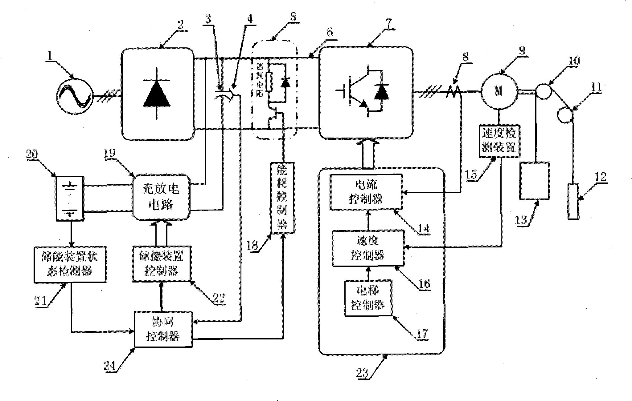
[0038] figure 1 It is a schematic diagram of the overall structure of Embodiment 1 of the elevator energy-saving device based on the cooperative control method proposed by the present invention. Depend on figure 1It can be seen that the external power supply 1 is connected to the three-phase AC side of the rectifier 2, the two-phase DC side of the rectifier 2 is connected to the two-phase DC side of the inverter 7 through the DC bus 6, and the smoothing DC capacitor 3 and the energy consumption circuit 5 are respectively across Connected to both ends of the DC bus 6, the bus voltage detection device 4 is arranged at both ends of the smoothing DC capacitor 3, the 3-phase AC side of the inverter 7 is connected to the elevator motor 9 through the current detection device 8, and the elevator motor 9 is connected to the elevator motor 9 through a specific structure. The traction sheave 10 is connected, and the car 13 and the counterweight 12 are suspended on both sides of the trac...

Embodiment 2

[0063] combine figure 1As shown, this embodiment is similar to Embodiment 1, and only the differences will be described below.

[0064] The cooperative controller 24 generates power instructions for the energy storage device controller 22 and the energy consumption controller 18 according to the DC bus voltage detected by the bus voltage detection device 4 and the working state of the energy storage device 20 detected by the energy storage device state detector 21 Values ​​are sent to the energy storage device controller 22 and the energy consumption controller 18 respectively. The energy storage device controller 22 controls the charging and discharging circuit 19 according to the power command value from the cooperative controller 24, so that the charging power of the energy storage device 20 (ie, the power passing through the charging and discharging circuit 19) tracks the command value. The energy consumption controller 18 controls the energy consumption circuit 5 accordi...

Embodiment 3

[0086] see Figure 4 As shown, this embodiment is similar to the second embodiment, and only the differences will be described below. The cooperative controller 24 calculates the elevator regenerative power P according to the DC bus voltage detected by the bus voltage detection device 4, the working state of the energy storage device 20 detected by the energy storage device state detector 21, and the elevator running state from the elevator control device 23 reg Based on this, the power command values ​​of the energy storage device controller 22 and the energy consumption controller 18 are generated according to certain rules and sent to the energy storage device controller 22 and the energy consumption controller 18 respectively. The energy storage device controller 22 controls the charging and discharging circuit 19 according to the power command value from the cooperative controller 24, so that the power of the energy storage device 20 (ie, the power passing through the cha...


PUM


Abstract

The invention discloses an elevator energy-saving device based on a cooperative control mode, which comprises an energy storage device (20), an energy storage device state detector (21), a charging and discharging circuit (19), an energy storage device controller (22), an energy consumption circuit (5), an energy consumption controller (18) and a cooperative controller, wherein the cooperative controller is used for realizing the cooperation and matching of a charging process of the energy storage device and an energy consumption process of the energy consumption circuit; instruction values of the energy storage device controller and the energy consumption controller are generated by the cooperative controller according to a running condition of an elevator; and according to the instruction values, the charging process of the energy storage device (20) and the energy consumption process of the energy consumption circuit (5) are performed in the cooperative control mode. The elevator energy-saving device can be used for realizing the energy conservation of the elevator, efficiently relieving fierce fluctuation of a bus voltage and coping with a specific situation that a regenerated current or regenerated power of an elevator motor is beyond an allowed scope of the energy storage device (20) and the charging and discharging circuit (19).

Description

technical field [0001] The invention relates to an elevator energy-saving device, in particular to an elevator energy-saving device that controls an energy storage device and a regeneration circuit in a coordinated manner. Background technique [0002] In recent years, it has become a research hotspot in the elevator industry to use the energy storage device added in the main loop of the elevator drive to process the regenerative energy generated during the operation of the elevator and realize the energy saving of the elevator. Such as Chinese Invention Patent Application Publications CN 101381046A, CN 1845417A, CN1946625A, Chinese Invention Patent Specifications CN 100593504C, CN 100450907C, CN1229275C and International Application Specifications WO2010 / 019122A1, WO2010 / 019123A1, WO2010 / 019271WO, etc. [0003] Through proper control, the energy storage device stores regenerative energy during the regenerative operation of the elevator motor, and releases the stored energy ...

Claims


Application Information

Patent Timeline
Patent Type & Authority Patents(China)
IPC IPC(8): B66B5/00B66B1/06H02J15/00
Inventor 陈玉东
Owner SHANGHAI MITSUBISHI ELEVATOR CO LTD
Why Eureka
Try Eureka