Photobioreactor and photobiology culture system

A technology of photobioreactor and photobiological cultivation, which is applied in the field of photobiological cultivation, can solve the problems of high power consumption and poor aeration effect, achieve the effect of convenient cleaning and harvesting, and improve the light receiving efficiency

Active Publication Date: 2012-03-14
ENN SCI & TECH DEV
View PDF3 Cites 7 Cited by
  • Summary
  • Abstract
  • Description
  • Claims
  • Application Information

AI Technical Summary

Problems solved by technology

[0006] The embodiment of the present invention provides a photobioreactor and its preparation method, photobiological cultivation s

Method used


Image

  • Photobioreactor and photobiology culture system
  • Photobioreactor and photobiology culture system
  • Photobioreactor and photobiology culture system

Examples


Embodiment 1

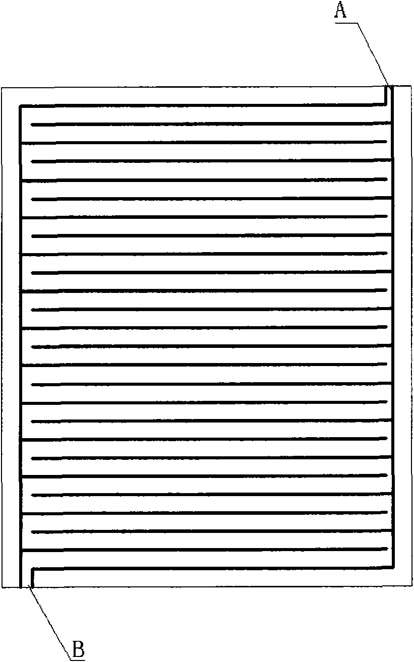
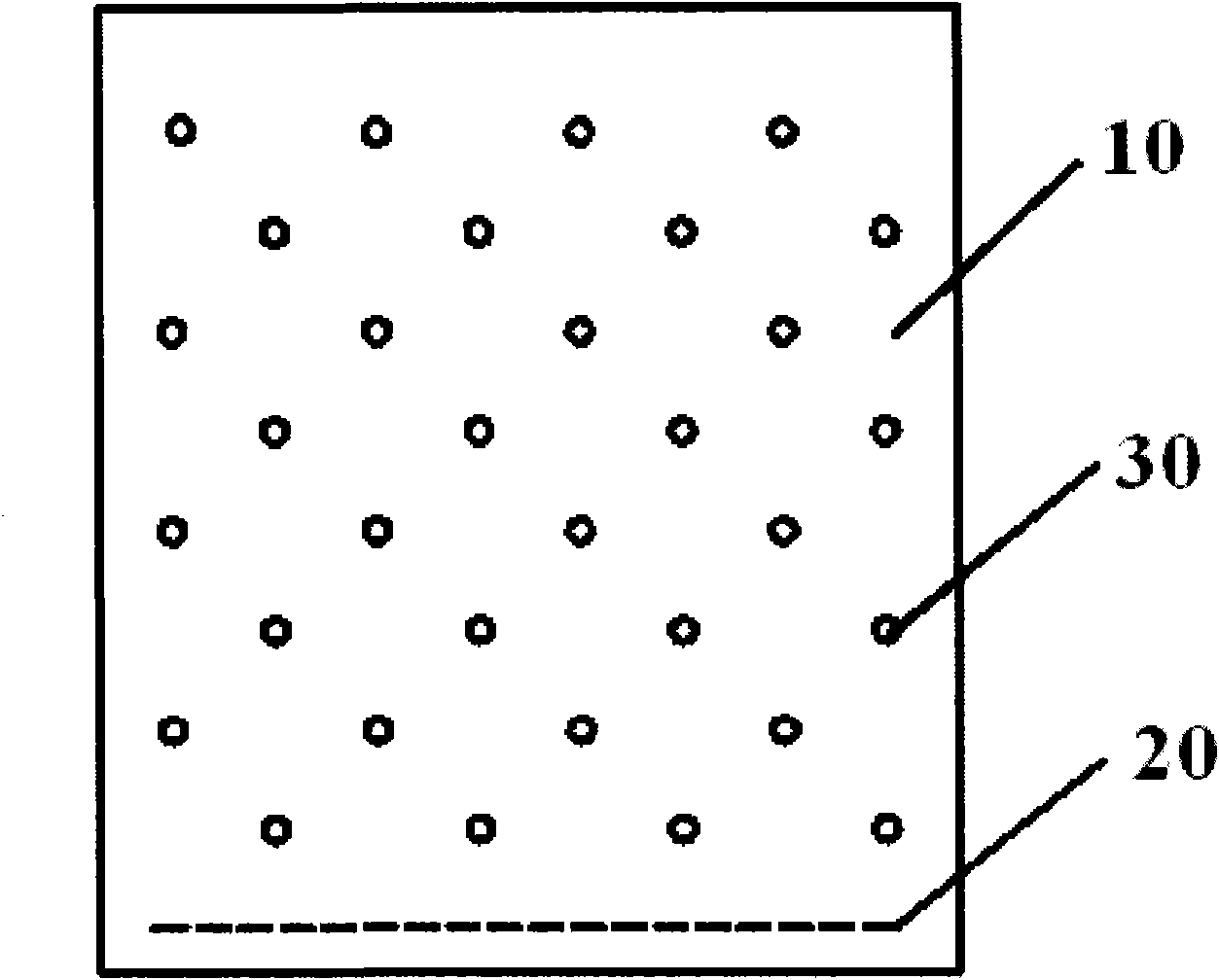
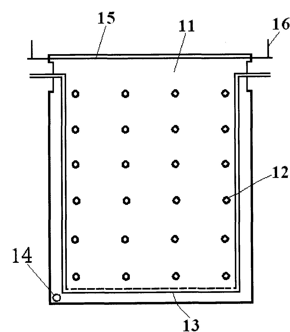
[0037] The photobioreactor provided by Embodiment 1 of the present invention has a structure such as image 3 As shown, it includes: a flexible film 11, a plurality of isolation points 12, an aeration device 13, a liquid inlet and outlet 14, and a suspension member composed of a suspension rod 15 and a suspension cable 16.

[0038]The above-mentioned flexible film 11 can be any transparent or translucent film such as polyethylene PE film, polyvinyl chloride PVC film, polyurethane PU film; and at least one side of the films on both sides of the photobioreactor is a transparent or translucent material; The sealing edges of the above-mentioned flexible film 11 are sealed by heat sealing or by sealing clips.

[0039] That is, the lower part and both side edges of the two flexible films 11 can be heat-sealed or clamped with sealing clips to form a fluid-connected bag-like container. It can also be sealed as a cylindrical film with a piece of flexible film, or an integrated cylindr...

Embodiment 2

[0046] The photobioreactor provided by the second embodiment of the present invention has a structure such as Figure 4 As shown, it includes: a flexible film 21, a plurality of isolation points 22, an aeration device 23, a liquid inlet and outlet 24, and a suspension member composed of a suspension rod 25 and a suspension cable 26.

[0047] It differs from the photobioreactor provided in Example 1 in that its aeration device 23 is a straight air pipe, and its inlets and outlets are located at the bottom. In the first embodiment, the aeration device 23 is a U-pipe ventilation pipe, and its inlet and outlet are located at the upper part of the photobioreactor.

[0048] A plurality of isolation points 22 are arranged between the flexible films 21 . The difference from Embodiment 1 is that multiple isolation points 22 can be formed by setting at least one pair of uprights 101 , 102 (see FIG. 9 , at the front and back sides corresponding to multiple isolation points 22 ). Specif...

Embodiment 3

[0053] The photobioreactor provided by Embodiment 3 of the present invention has a structure such as Figure 5 As shown, it includes: a flexible film 31 , a plurality of isolation points 32 , an aeration device 33 , a liquid inlet and outlet 34 , and a suspension member composed of a suspension hole 35 .

[0054] It differs from the photobioreactor provided in Example 1 in that its suspension member is a suspension hole 35 . The suspension of the reactor is directly realized through the suspension hole 35 . As shown in the figure, the upper part of the flexible film 31 is pointed, and a hanging hole is provided at the pointed corner.

[0055] The rest of the structure of the photobioreactor is the same as that of Embodiment 1, and will not be repeated here.


PUM

PropertyMeasurementUnit
Diameteraaaaaaaaaa

Abstract

The invention discloses a bag photobioreactor made of flexible films and a photobiology culture system comprising the same. A fluid inlet/outlet for injecting and discharging photobiology culture fluid is formed on the photobioreactor, and an aerating device is arranged in the photobioreactor. The photobioreactor is characterized in that a plurality of isolation points are formed in the photobioreactor and are used for dividing the photobiology culture fluid in the photobioreactor into a plurality of fluid areas communicated with each other; the aerating device is used for injecting gases into the photobiology culture fluid via the bottom of the photobioreactor; and the gases include the reaction gases required for photobiology growth. The photobioreactor has the following beneficial effects: the gases injected by the aerating device can flow through each fluid area smoothly from bottom to top, so that the photobiology and reaction gases in the photobiology culture fluid can fully react, and the photobiology culture fluid can be fully stirred by the gases, thus improving the light intercepting efficiency of the photobiology.

Description

technical field [0001] The invention relates to the technical field of photobiological cultivation, in particular to a film-type photobioreactor and a preparation method thereof, a photobiological cultivation system and method. Background technique [0002] At present, the industrial production of microalgae still generally adopts the open pond culture system, which has the advantages of less investment, simple operation and easy production, but has the following disadvantages: (1) It is easily affected by the external environment, and it is difficult to maintain a suitable temperature (2) It will be polluted by dust, insects and miscellaneous bacteria, and it is difficult to maintain high-quality single algae culture; (3) Water is easy to evaporate; (4) The ratio of light area to culture volume is low, light energy and CO 2 The utilization rate is not high, and high-density cultivation cannot be realized; (5) harmful substances such as heavy metals are easy to accumulate in...

Claims


Application Information

Patent Timeline
IPC IPC(8): C12M1/00C12M1/04
CPCC12M21/02C12M23/14C12M27/18C12M29/06
Inventor 朱振旗王垚陈彦平
Owner ENN SCI & TECH DEV
Why Eureka
Try Eureka