
Air flow net forming machine

A web forming machine and airflow technology, which is applied in textiles and papermaking, fiber processing, fiber feeding, etc., can solve the problems of affecting web forming efficiency, increasing the output resistance of cotton web, and blocking the cotton inlet channel, etc.

Active Publication Date: 2012-10-10
JIANGSU YINGYANG NONWOVEN MASCH CO LTD
View PDF6 Cites 11 Cited by
  • Summary
  • Abstract
  • Description
  • Claims
  • Application Information

AI Technical Summary

Problems solved by technology

[0004] But, the above-mentioned patent scheme still has the following shortcoming: the one, because will be used to lead out in the cotton passage that is communicated with the cotton passage, mixed in the non-woven fiber The wind pressure regulating box of the air is arranged on the lower side of the cotton inlet channel, and the output curtain is arranged at the bottom of the cotton inlet channel (the specification of the patent Figure 1 and Figure 2), so it is a structure of side draft, and practice has proved that side draft will greatly affect the uniformity of the non-woven fiber layer delivered to the output curtain, It will affect the uniformity of the final product, that is, the weight of non-woven fabrics; the second is that the side draft will increase the output resistance of the cotton web, thereby affecting the web forming efficiency, and there is also the risk of blocking the cotton inlet channel

Method used


Image

  • Air flow net forming machine
  • Air flow net forming machine

Examples


Embodiment Construction

[0020] In order to enable the examiners of the patent office, especially the public, to understand the technical essence and beneficial effects of the present invention more clearly, the applicant will describe in detail the following in the form of examples, but none of the descriptions to the examples is an explanation of the solutions of the present invention. Any equivalent transformation made according to the concept of the present invention which is merely formal but not substantive shall be regarded as the scope of the technical solution of the present invention.

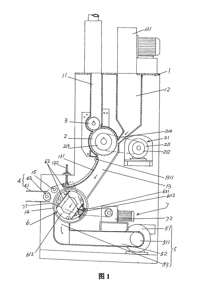
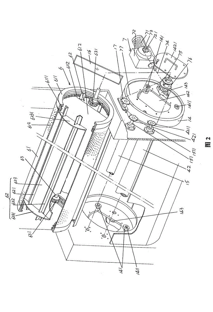
[0021] please see figure 1 and figure 2 , given a rack 1, given by figure 1 As shown, a cotton mixing box 11 is provided on the top of the frame 1, and the non-woven fiber cotton that is loosened by the opener of the previous process is introduced in the cotton mixing box 11. Again, an air inlet duct 12 is provided on the top of the frame 1, by figure 1 The blower 121 is shown to introduce press...


PUM


Abstract

The invention relates to an air flow net forming machine, which belongs to the technical field of textile machinery and comprises a machine frame, a large pin roll, a small pin roll, an output curtain and a draft mechanism, wherein the machine frame is provided with a cotton mixing box, an air inlet box and a cotton inlet passage, the large pin roll and the small pin roll are arranged on the machine frame, the output curtain is matched and arranged on the machine frame, and the draft mechanism is arranged at the bottom of the machine frame. The air flow net forming machine is characterized byalso comprising a dust cage and a dust cage driving mechanism, wherein the dust cage is arranged on the machine frame and corresponds to a position under the cotton inlet passage, the dust cage driving mechanism is arranged at the lower part of the machine frame and is in transmission connection with the dust cage, the output curtain corresponds to the side part in the length direction of the dust cage, and the draft mechanism corresponds to the bottom in the length direction of the dust cage. The air flow net forming machine has the advantages that the side draft in the prior art is changed into bottom air draft, so the non-woven fiber cotton layer reaching the output curtain is more uniform to ensure the uniformity of the gram weight of the non-woven products. Because of the adoption ofthe bottom draft, the output resistance of a cotton net can be reduced, the net forming speed is favorably accelerated, and in addition, a blockage phenomenon of the non-woven fiber cotton in the cotton output passage can be avoided.

Description

technical field [0001] The invention belongs to the technical field of textile machinery, and in particular relates to an air-laid machine. Background technique [0002] The air-laid machine is also called an air-flow cotton feeder, or even simply called a cotton feeder. In a complete non-woven product production line, the function of the air-laid machine is to form a uniform non-woven fabric from the pre-opened non-woven fiber. The state of the cotton net layer is sent to the output curtain (the industry is accustomed to call it the net transmission curtain), and the output curtain is sent to the final setting equipment to make non-woven products such as non-woven fabrics. [0003] China Utility Model Patent Authorization Announcement No. CN2663451Y recommends a cotton feeder with improved structure. The achievement of this patent scheme is that it can reduce the air content in the non-woven fiber layer delivered to the output curtain, so as to ensure that the cotton web is...

Claims


Application Information

Patent Timeline
Patent Type & Authority Patents(China)
IPC IPC(8): D01G23/08
Inventor 范立元
Owner JIANGSU YINGYANG NONWOVEN MASCH CO LTD
Learn More