Loop heat pipe

A loop heat pipe and pipeline technology, applied in circuits, indirect heat exchangers, lighting and heating equipment, etc., can solve the problems of loop heat pipe temperature fluctuations, pipeline blockage, evaporator drying and burning, etc., and achieve the effect of ensuring stability

Inactive Publication Date: 2012-03-14
FU ZHUN PRECISION IND SHENZHEN +1
View PDF5 Cites 3 Cited by
  • Summary
  • Abstract
  • Description
  • Claims
  • Application Information

AI Technical Summary

Problems solved by technology

Therefore, when the liquid returns to the evaporator through the liquid pipeline, the intermittent liquid supply to the evaporator is caused by the existence of the gas plug, resulting in temperature fluctuations in the loop heat pipe, and in severe cases, it will cause the evaporator to dry up and burn.
In the prior art, there is a capillary structure in the liquid pipeline to prevent the formation of gas plugs, but this method is easy to cause pipeline blockage, and when the length of the liquid pipeline is large, it will increase the cost and difficulty of manufacturing, and the effect is not ideal

Method used


Image

  • Loop heat pipe
  • Loop heat pipe
  • Loop heat pipe

Examples


Embodiment Construction

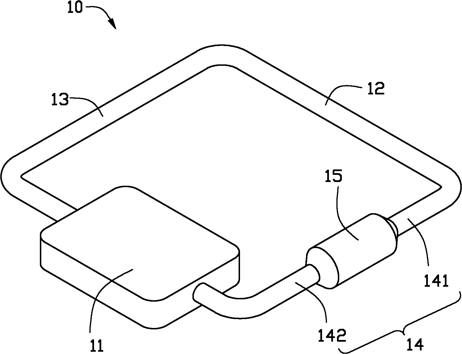
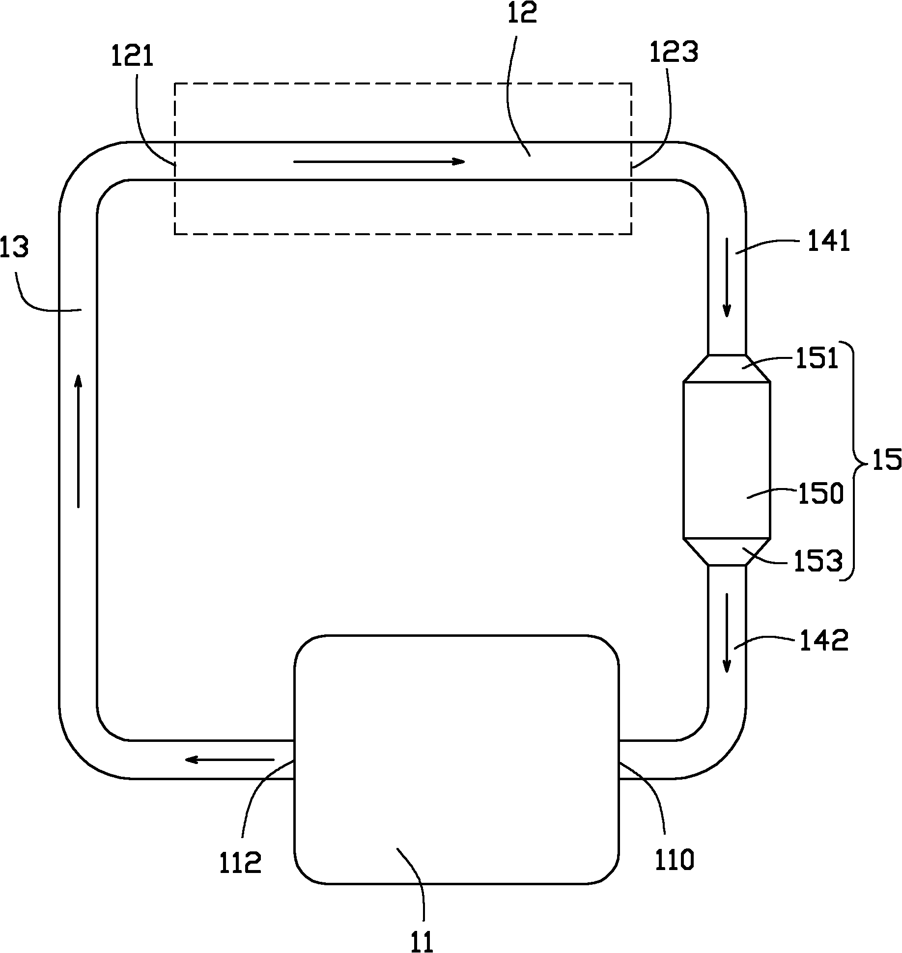
[0014] Please refer to figure 1 and figure 2 , The loop heat pipe 10 in the first embodiment of the present invention includes an evaporating part 11 , a condensing part 12 , a vapor pipeline 13 , a liquid pipeline 14 and a drip funnel part 15 .

[0015] The evaporator 11 is rectangular, and includes an evaporator inlet 110 connected to one end of the liquid line 14 and an evaporator outlet 112 connected to one end of the vapor line 13 . The evaporator 11 is thermally connected with a heat-generating electronic component, such as a CPU (not shown). The condensing part 12 is in the shape of a circular tube, which is parallel to the evaporating part 11 . The condenser 12 includes a condenser inlet 121 connected to the other end of the vapor pipeline 13 and a condenser outlet 123 connected to the other end of the liquid pipeline 14 . The outer surface of the condenser part 12 can be combined with a heat dissipation element, such as heat dissipation fins (not shown) pierced on...


PUM


Abstract

The invention relates to a loop heat pipe. The loop heat pipe comprises an evaporation part, a condensation part, a vapor pipeline and a liquid pipeline, wherein the vapor pipeline and the liquid pipeline are arranged between the evaporation part and the condensation part; the evaporation part is connected with the condensation part to form a loop; the loop is filled with a working medium; the liquid pipeline is connected with a dripping hopper part; the volume of the dripping hopper part is greater than that of the liquid pipeline in the same length; and the dripping hopper part is used for separating mixed gaseous working medium and liquid working medium which are delivered by the liquid pipeline.

Description

technical field [0001] The invention relates to a heat transfer element, in particular to a loop heat pipe. Background technique [0002] With the continuous improvement of the power of electronic components such as central processing units, the problem of heat dissipation has been paid more and more attention by people. A loop heat pipe (LHP) is used as an effective heat transfer element in the field of heat dissipation due to its efficient heat conduction performance. [0003] Generally, the loop heat pipe includes an evaporator, a condenser, and a vapor line and a liquid line disposed between the evaporator and the condenser. The vapor pipeline and the liquid pipeline connect the evaporating part and the condensing part to form a circuit, and the circuit is filled with working medium. The evaporation part is thermally connected with a heating electronic component. When the evaporation part of the loop heat pipe is heated, the working medium in it absorbs heat, evaporat...

Claims


Application Information

Patent Timeline
Patent Type & Authority Applications(China)
IPC IPC(8): F28D15/02H05K7/20
CPCF28D15/0266H01L23/427H01L2924/0002H01L2924/00
Inventor 许超胡江俊王德玉侯春树
Owner FU ZHUN PRECISION IND SHENZHEN
Why Eureka
Try Eureka