
Relaxation oscillator with low power consumption

An oscillator and relaxation type technology, which is applied in the direction of electrical components, electric pulse generation, pulse generation, etc., can solve the problems of many DC current paths, the inability to achieve low power consumption, and affect the accuracy of frequency, etc., to reach the power consumption part Improved effect

Active Publication Date: 2012-03-14
ELAN MICROELECTRONICS CORPORATION
View PDF7 Cites 21 Cited by
  • Summary
  • Abstract
  • Description
  • Claims
  • Application Information

AI Technical Summary

Problems solved by technology

[0004] It is known that the technologies disclosed in US Patent Nos. US 6362697, US 6680656, and US 6891443 cannot meet the demand for low power consumption due to the excessive number of DC current paths.
Although the US Patent No. US 7443260 can meet the demand for low power consumption, its output oscillation frequency cannot maintain the linear relationship of T=RC with respect to resistance and capacitance, so it is easily affected by many factors such as manufacturing process, voltage, temperature, etc. The accuracy of its frequency

Method used


Image

  • Relaxation oscillator with low power consumption
  • Relaxation oscillator with low power consumption
  • Relaxation oscillator with low power consumption

Examples


Embodiment Construction

[0019] The present invention will be further described below in conjunction with the accompanying drawings and embodiments.

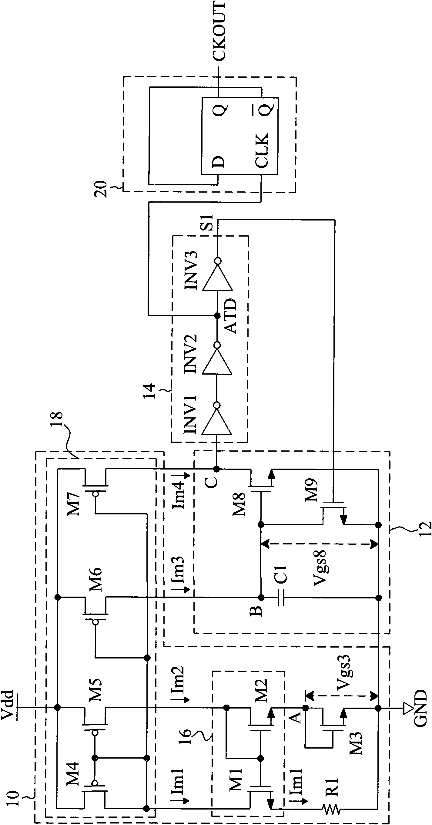
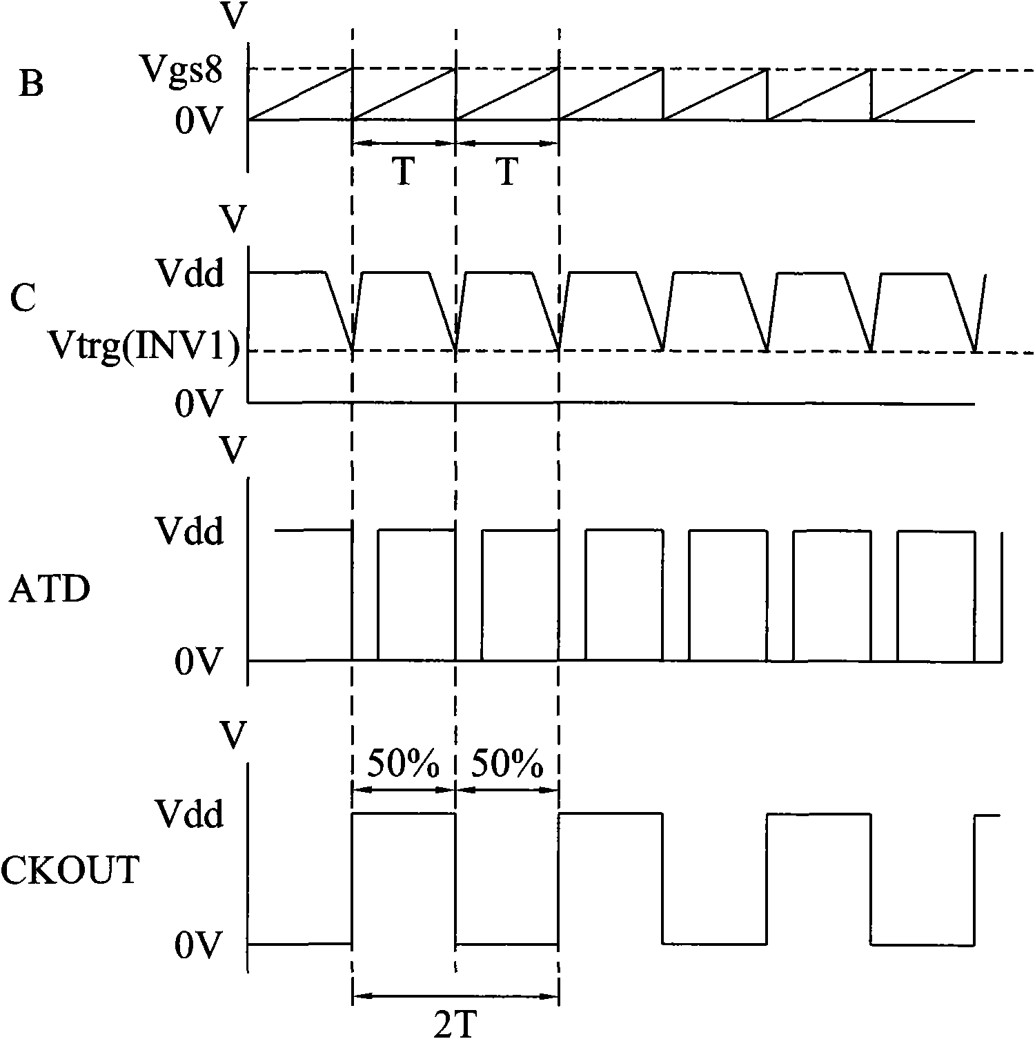
[0020] figure 1 is an embodiment of the relaxation oscillator of the present invention. The relaxation oscillator includes a current source generating circuit 10 , a charging and discharging circuit 12 and a delay circuit 14 . The current source generating circuit 10 utilizes the gate and drain of the transistor M3 to be short-circuited to form an assembly similar to a bias diode, so that the voltage across the node A to the ground point GND is Vgs3, and the transistors M1 and M2 of the current mirror 16 are designed to have the same characteristics, Therefore, the voltage across the drain of the transistor M1 to the ground GND is also Vgs3 at both ends of the resistor R1, thus generating a bias current Im1=(Vgs3 / R1) of the current source. The transistors M4, M5, M6, and M7 of design current mirror 18 all have identical characteristics again, i.e. (W / ...


PUM


Abstract

The invention relates to a relaxation oscillator with low power consumption, wherein the relaxation oscillator is invented for solving problems like high power consumption and the like in the prior art. The relaxation oscillator comprises a current source generation circuit, a charge and discharge circuit and a delay circuit. The current source generation circuit utilizes a cross voltage formed by connection of a gate and a drain of a first transistor so as to enable a resistor to generate a bias current; the charge and discharge circuits utilize a mirroring current of the bias current to enable a capacitance to be charged, so that a second transistor that has the same characteristics as the first transistor to be conducted; and with utilization of the delay circuit that is connected between a drain of the second transistor and a gate of a third transistor, the capacitance is able to be charged and discharged periodically, so that an oscillation frequency that is independent of a power source voltage is generated and a low power consumption effect is realized.

Description

technical field [0001] The invention relates to a relaxation oscillator, in particular to a relaxation oscillator with low power consumption. Background technique [0002] Due to the improvement of process control and cost reduction in recent years, internal resistors and capacitors are actively used as components of relaxation oscillators in microcontroller units (MCU) and other circuits, and frequency calibration methods are used to calibrate (trimming ) process changes in resistance and capacitance in order to obtain accurate frequency. The relaxation type oscillator using internal resistance and capacitance is widely used in microcontroller units and other circuits to replace the crystal oscillator (crystal oscillator) as the oscillation source generated by the internal frequency of the IC. In addition, this circuit is also used as a micro A watch dog timer (WDT) or sleep mode timer (sleep mode timer) in the control unit. [0003] In the design of general relaxation os...

Claims


Application Information

Patent Timeline
IPC IPC(8): H03K3/012
Inventor 王俊淇江宗殷
Owner ELAN MICROELECTRONICS CORPORATION
Learn More