Method and device for demodulating pilot-tone modulation signals

An optical modulation and signal technology, applied in the field of optical communication network, can solve the problem of extracting optical modulation top signal and so on

Active Publication Date: 2012-03-14
ZTE CORP
View PDF3 Cites 15 Cited by
  • Summary
  • Abstract
  • Description
  • Claims
  • Application Information

AI Technical Summary

Problems solved by technology

[0006] The present invention provides a method and device for demodulating the optical modulation signal, which is used to solve the problem of how to extract the optical modulation signal under the influence of noise in the optical network containing the frequency of the optical modulation signal

Method used


Image

  • Method and device for demodulating pilot-tone modulation signals
  • Method and device for demodulating pilot-tone modulation signals
  • Method and device for demodulating pilot-tone modulation signals

Examples


Embodiment 1

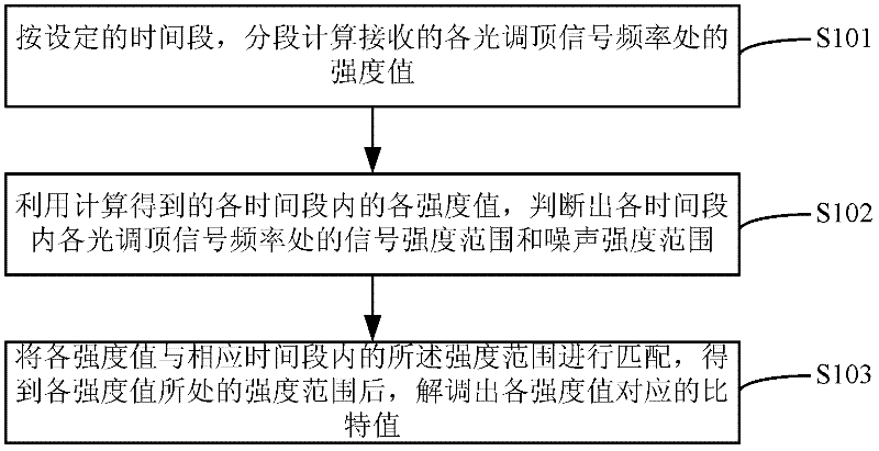
[0080] In the embodiment of the present invention, the modulation method adopted by the signal transmission source end is: use frequency f1 as bit information "1", use frequency f2 as bit information "0", and the signal transmission source end loads a schematic diagram of the frequency of the optical modulation signal Such as Figure 4 shown. In this embodiment, f1 is used as bit information 1, and f2 is used as bit information 0, which is only one of many modulation methods. The source end can use other modulation methods according to specific applications. For example, f1 is used as bit information 1 without top modulation. Frequency is used as bit information 0, etc.

[0081] In the embodiment of the present invention, when receiving such as Figure 4 When the frequency information of the optical modulation signal in the modulation mode is shown, the method for demodulating the optical modulation signal includes:

[0082] Step 1, using the FFT or DFT algorithm to calcula...

Embodiment 2

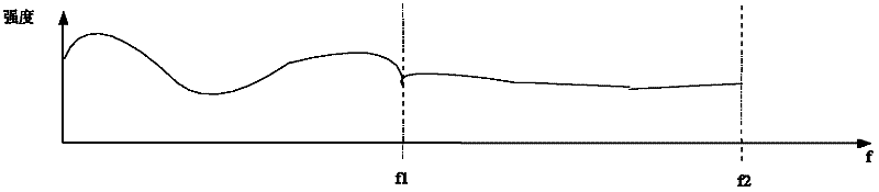
[0090] In the embodiment of the present invention, the modulation mode adopted by the signal transmission source end is as follows: the frequency f1 is used as the bit information "1", and "0" is indicated when there is no tuning frequency. The schematic diagram of the signal transmission source loading the optical tuning signal frequency is as follows Figure 6 shown.

[0091] In the embodiment of the present invention, when receiving such as Figure 6 When the frequency information of the optical modulation signal in the modulation mode is shown, the method for demodulating the optical modulation signal includes:

[0092] Step 1, utilize the FFT or DFT algorithm to calculate the intensity value at the frequency (f1) of each light modulation signal frequency (f1) place that is received;

[0093] In this embodiment, set the time period as the time value of receiving the 6-bit signal, wherein, for a certain period of time, calculate the intensity value at the frequency of each...

Embodiment 3

[0099] The implementation of this embodiment is based on the premise of any of the above-mentioned embodiments, and is used to judge whether the optical top adjustment signal is lost or the top adjustment signal conflicts through the obtained intensity range, specifically:

[0100] In this embodiment, it is assumed that the intensity range at a certain frequency in several consecutive time periods is counted by using the method described in the above-mentioned embodiment 2, and the number of intensity range distributions in this period of time is obtained.

[0101] Such as Figure 8 As shown, the intensity range of the optical modulation signal frequency f1 is calculated for several consecutive periods of time. It can be seen from the figure that the signal intensity value of f1 is within a certain intensity range during this period of time, and according to the signal transmission source modulation As a rule, the frequency of f1 should not all be the same value during this pe...


PUM


Abstract

The invention discloses a method and device for demodulating pilot-tone modulation signals. The method comprises the following steps of: calculating an intensity value at a frequency position of each received pilot-tone modulation signal in a subsection manner according to a set time period; judging a signal intensity range and a noise intensity range at the frequency position of the received pilot-tone modulation signal at each time period according to the received intensity value during each time period; matching each intensity value with the intensity range within the corresponding time period to obtain the intensity range of each intensity value so that a bit value corresponding to each intensity value is demodulated. The device comprises an intensity value calculation module, an intensity range obtaining module and a bit information obtaining module. According to the method and device for demodulating the pilot-tone modulation signals, the pilot-tone modulation signals are demodulated regardless of the distribution state of noise by using the intensity range of dynamic regulation noise and the intensity range of the pilot-tone modulation signals; furthermore, the pilot-tone modulation signals are demodulated by using a corresponding relation between the same frequency of the pilot-tone modulation signals and a wavelength.

Description

technical field [0001] The invention relates to the technical field of optical communication networks, in particular to a method and device for demodulating an optical top adjustment signal. Background technique [0002] With the development of WDM (Wavelength Division Multiplex, wavelength division multiplexing), the current optical communication network can simultaneously transmit multiple optical signals or optical channels of different wavelengths in the same optical fiber, and based on ROADM (Reconfigurable Optical Add-Drop Multiplexer , reconfigurable optical add-drop multiplexer) technology facilitates the on-demand configuration of each wavelength in optical communication, so that the wavelength in the optical network does not maintain the same path between two sites, or a certain wavelength is not allocated forever For a certain 2 sites. [0003] In order to carry out network topology identification and optical channel detection, it is possible to superimpose low-f...

Claims


Application Information

Patent Timeline
Patent Type & Authority Applications(China)
IPC IPC(8): H04B10/08H04B10/12H04B10/075
CPCH04B10/0775H04B2210/075
Inventor 尚迎春
Owner ZTE CORP
Why Eureka
Try Eureka