Ultrasonic oval vibrating mechanism for assisting diamond cutter in ultra-precision cutting

A diamond tool, elliptical vibration technology, used in the attachment of tool holders, tools for lathes, fluids that utilize vibration, etc. Restrict the quality of the machined surface and other problems, and achieve the effects of good vibration conductivity, no reflection, and large lateral stiffness

Inactive Publication Date: 2012-03-21
TSINGHUA UNIV
View PDF6 Cites 21 Cited by
  • Summary
  • Abstract
  • Description
  • Claims
  • Application Information

AI Technical Summary

Problems solved by technology

Most of the existing elliptical vibration cutting devices adopt the transducer-horn structure, which works at the resonant frequency of the structure, cannot change the vibration frequency, and is difficult to adjust the elliptical trajectory, and cannot adapt to cutting parameters, processing materials and surface shapes. Variety
At the same time, the existing resonant vibrating cutting device is generally a circular cross-section rod-shaped structure or its combination, which is not easy to install. It is necessary to design a special tool holder to fix the cutting device, and the structure of the cutting device is not well stressed and rigid, which restricts the machining surface. quality improvement

Method used


Image

  • Ultrasonic oval vibrating mechanism for assisting diamond cutter in ultra-precision cutting
  • Ultrasonic oval vibrating mechanism for assisting diamond cutter in ultra-precision cutting
  • Ultrasonic oval vibrating mechanism for assisting diamond cutter in ultra-precision cutting

Examples


Embodiment Construction

[0017] The present invention will be described in detail below in conjunction with the accompanying drawings and embodiments.

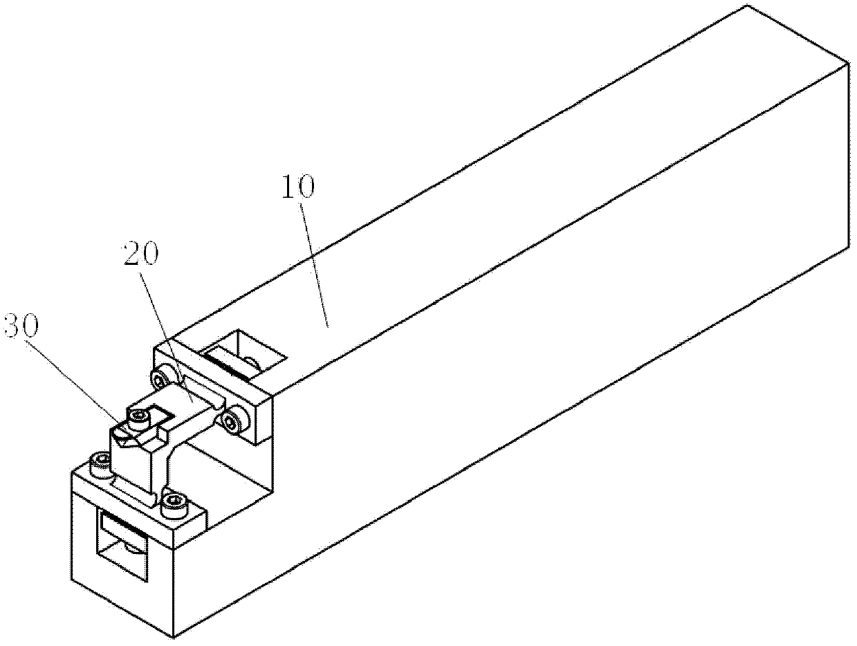
[0018] Such as figure 1 As shown, the present invention mainly includes a handle 10 , a vibration unit 20 and a tool 30 ; the vibration unit 20 is arranged on the handle 10 , and the tool 30 is arranged on the vibration unit 20 .

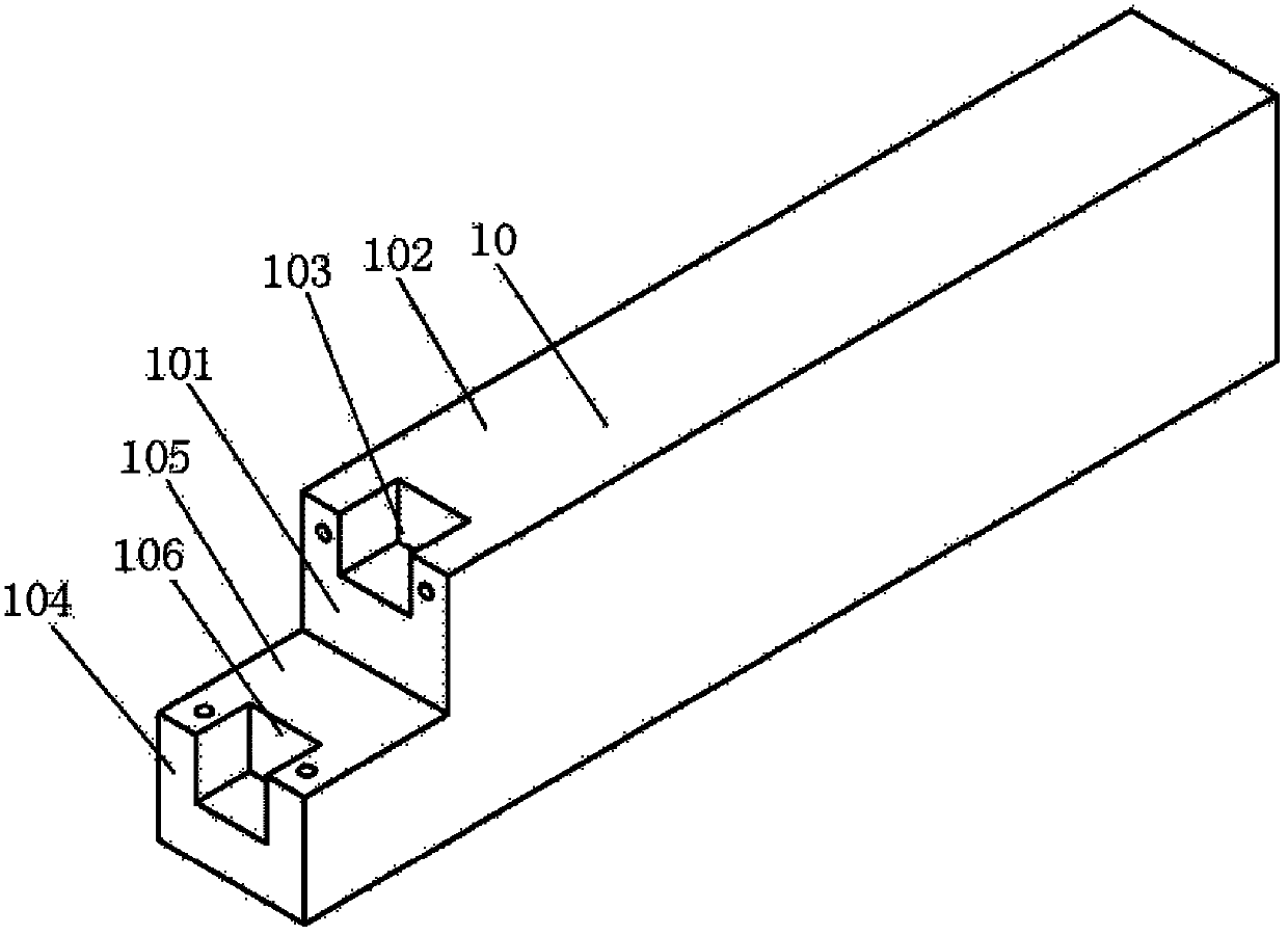
[0019] Such as figure 2 As shown, one end of the knife handle 10 of the present invention is stepped, and a groove 103 is arranged on the vertical surface 101 and the horizontal surface 102 of the upper step, and a groove is also arranged on the vertical surface 104 and the horizontal surface 105 of the lower step. 106. The size and shape of the tool holder 10 of the present invention are the same as those of conventional cutting, so it can be directly installed on a conventional tool holder.

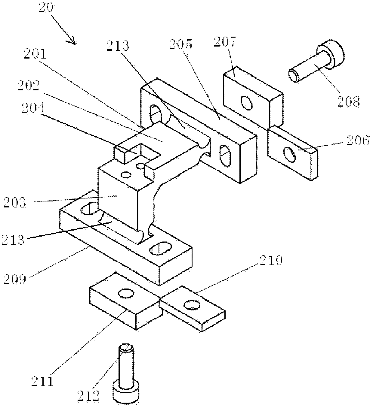
[0020] Such as image 3 , Figure 4 As shown, the vibrating unit 20 of the present invention mainly includes a vibrating body...


PUM


Abstract

The invention relates to an ultrasonic oval vibrating mechanism for assisting a diamond cutter in ultra-precision cutting. The ultrasonic oval vibrating mechanism is characterized by comprising a cutter handle, a vibrating unit and a cutter, wherein one end of the cutter handle has a step-shaped structure; the vertical surfaces and the horizontal surfaces of an upper layer step and a lower layer step are provided with grooves; the vibrating unit comprises a vibrating body consisting of a transverse vibrating rod and a longitudinal vibrating rod which are vertical to each other; the top surface of the joint of the transverse vibrating rod and the longitudinal vibrating rod is provided with a groove; the end part of the transverse vibrating rod is provided with a transverse end face; the other side of the transverse end face is provided with a transverse excitation source and a transverse cover plate in sequence; the end part of the longitudinal vibrating rod is provided with a longitudinal end face; the other side of the longitudinal end face is provided with a longitudinal excitation source and a longitudinal cover plate in sequence; the transverse end face is formed on the vertical surface of the upper layer step of the cutter handle; the transverse cover plate and the transverse excitation source are positioned in the groove of the upper layer step; the longitudinal end faceis formed on the horizontal surface of the lower layer step of the cutter handle; the longitudinal cover plate and the longitudinal excitation source are positioned in the groove of the lower layer step; and the cutter is arranged in the groove at the joint of the transverse vibrating rod and the longitudinal vibrating rod.

Description

technical field [0001] The invention relates to an ultrasonic assisted cutting mechanism, in particular to an ultrasonic elliptical vibration mechanism for assisting ultra-precision cutting of a diamond tool. Background technique [0002] Natural single-point diamond tools are widely used in the field of ultra-precision machining, because the radius of the single-point diamond cutting edge is extremely small, and the corresponding ultra-precision CNC machine tools can be used to process non-ferrous metals to obtain a surface shape accuracy of less than 0.5 μm and a surface finish of less than 5nm ultra-precise mirror. However, the current single-point diamond cutting technology is difficult to process iron-based materials, because during the machining process, a severe thermal-chemical reaction occurs between the carbon atoms of the diamond tool and the iron atoms of the workpiece, which causes severe wear of the tool, and the cutting cannot be continued. very bad. In orde...

Claims


Application Information

Patent Timeline
Patent Type & Authority Applications(China)
IPC IPC(8): B23B27/00B06B1/06
Inventor 李勇杨锦荣谢晓丹
Owner TSINGHUA UNIV
Why Eureka
Try Eureka