Tube body forming structure of fluorescent tube processor

A fluorescent lamp tube and processing machine technology, applied in glass forming, glass re-forming, manufacturing tools and other directions, can solve the problems of low processing efficiency, high labor intensity of workers, etc., and achieve fast forming speed, simple structure and energy saving. Effect

Inactive Publication Date: 2012-03-21
CHANGSHU CHIKUSHI MACHINERY
View PDF0 Cites 0 Cited by
  • Summary
  • Abstract
  • Description
  • Claims
  • Application Information

AI Technical Summary

Problems solved by technology

The disadvantages are: because the workers usually process one person, one furnace and one mold, the labor intensity is high and the processing efficiency is low. In addition, it is not conducive to savi

Method used


Image

  • Tube body forming structure of fluorescent tube processor
  • Tube body forming structure of fluorescent tube processor

Examples


Example Embodiment

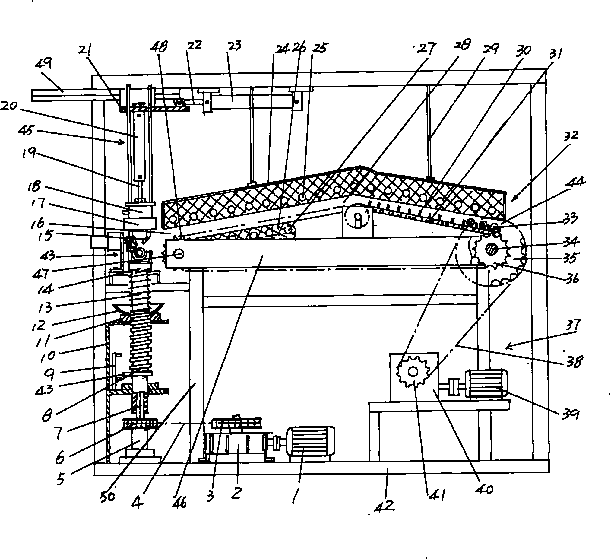
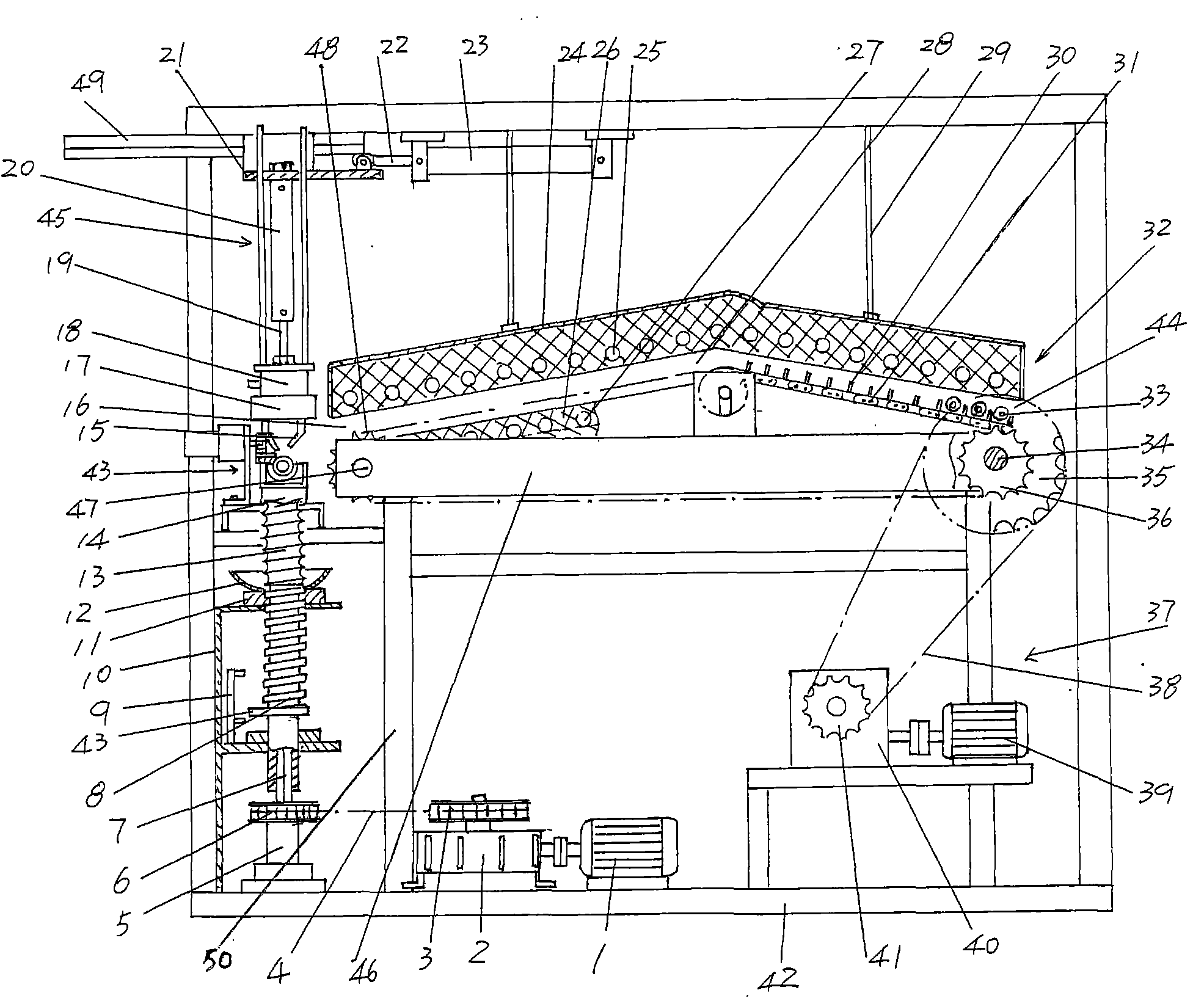
[0010] Please refer to the accompanying drawings. Taking the position state shown in the figure as an example, the spiral tube forming mechanism of the present invention is arranged on the left side of the frame 42 of the tube processing machine, specifically: fixing to the frame The first motor 1 with forward and reverse rotation function at the bottom of 42 is connected to the power input shaft of the first reducer 2 through a coupling. The first reducer 2 is fixed at the bottom of the frame 42 and at the end of the first reducer 2. The first sprocket 3 is fixed on the first-stage power output shaft, one end of the first chain 4 is sleeved on the first sprocket 3, and the other end of the first chain 4 is sleeved on the second sprocket 6. The second sprocket 6 is fixed on the square shaft 7, the lower end of the square shaft 7 is pivoted on the shaft support 5, and the shaft support 5 is fixed on the frame 42, the upper end of the square shaft 7 is fixedly connected with the l...


PUM


Abstract

The invention discloses a tube body forming structure of a fluorescent tube processor and belongs to the technical field of processing machines of glass products. The tube body forming structure comprises a first motor, a first speed reducer, a first chain wheel, a second chain wheel, a first chain, a shaft support seat, a square shaft, a screw, a screw signal acquisition device, a screw seat, nut beds, a protection bowel and a forming die, wherein the first motor is connected with the first speed reducer in a drive way and is arranged at the bottom of a frame of the fluorescent tube processor; the first chain wheel is fixedly arranged on a last-stage power output shaft of the first speed reducer; one end of the first chain is sleeved on the first chain wheel; the other end of the first chain is sleeved on the second chain wheel; the second chain wheel is fixedly arranged on the square shaft; the lower end of the square shaft is pivotally arranged on the shaft support seat; the shaft support seat is fixedly arranged on the frame; the upper end of the square shaft is connected with the lower end of the screw; the screw is arranged on the screw seat which is fixedly arranged on the frame through a pair of nut beds; the upper end of the screw is connected with the lower end of the forming die; a tube billet groove is formed on the end surface at the top end of the forming die; the protection bowl is fixedly arranged on one upper nut bed in the pair of nut beds and corresponds to the lower part of the forming die; the screw signal acquisition device is fixedly arranged on the screw seat and is matched with a bunter at the lower part of the screw; the screw signal acquisition device is a microswitch, a travel switch or a proximity switch; and the first motor is a forward-reverse motor. The tube body forming structure has the advantage that energy sources of a heating furnace for heating a tube billet of the fluorescent tube can be saved.

Description

technical field [0001] The invention belongs to the technical field of glass product processing machinery, and in particular relates to a tube body forming structure of a fluorescent lamp tube processing machine. Background technique [0002] The spiral lamp tube is mainly used to make energy-saving lamps or craft lamps. In the prior art, the processing of the spiral lamp tube is to heat the tube blank that needs to be formed on a high-temperature flame-breathing furnace or a flame-breathing lamp to soften the tube blank. To the extent that it can be formed, it is quickly placed on the forming die to form a spiral tubular structure. The disadvantages are: because the workers usually process one person, one furnace and one mold, the labor intensity is high and the processing efficiency is low. In addition, it is not conducive to saving energy. For example, when the workers put the heated tube blank into the mold During the forming process, the high-temperature flame-breathin...

Claims


Application Information

Patent Timeline
IPC IPC(8): C03B23/045
Inventor 朱雪忠
Owner CHANGSHU CHIKUSHI MACHINERY
Why Eureka
Try Eureka