
Gas turbine combustor

一种燃气轮机、燃烧器的技术,应用在燃烧器、燃烧器、气体燃料燃烧器等方向,能够解决点火特性及火焰传播特性下降等问题,达到提高点火特性及火焰传播特性、减少NOx的效果

Active Publication Date: 2014-07-30
MITSUBISHI POWER LTD
View PDF8 Cites 0 Cited by
  • Summary
  • Abstract
  • Description
  • Claims
  • Application Information

AI Technical Summary

Problems solved by technology

[0008] On the other hand, the ignition characteristics and flame propagation characteristics of the gas turbine at startup show that the greater the fuel concentration of the mixture gas (that is, the larger the fuel-air ratio), the better the characteristics, because the fuel concentration of the mixture gas in the mixing chamber is uniform in the premixed combustion There is a tendency to degrade the ignition characteristics and flame propagation characteristics when the gas turbine is started.

Method used


Image

  • Gas turbine combustor
  • Gas turbine combustor
  • Gas turbine combustor

Examples


Embodiment 1

[0040] refer to Figure 1 to Figure 5 The gas turbine combustor 4 according to the first embodiment of the present invention will be described.

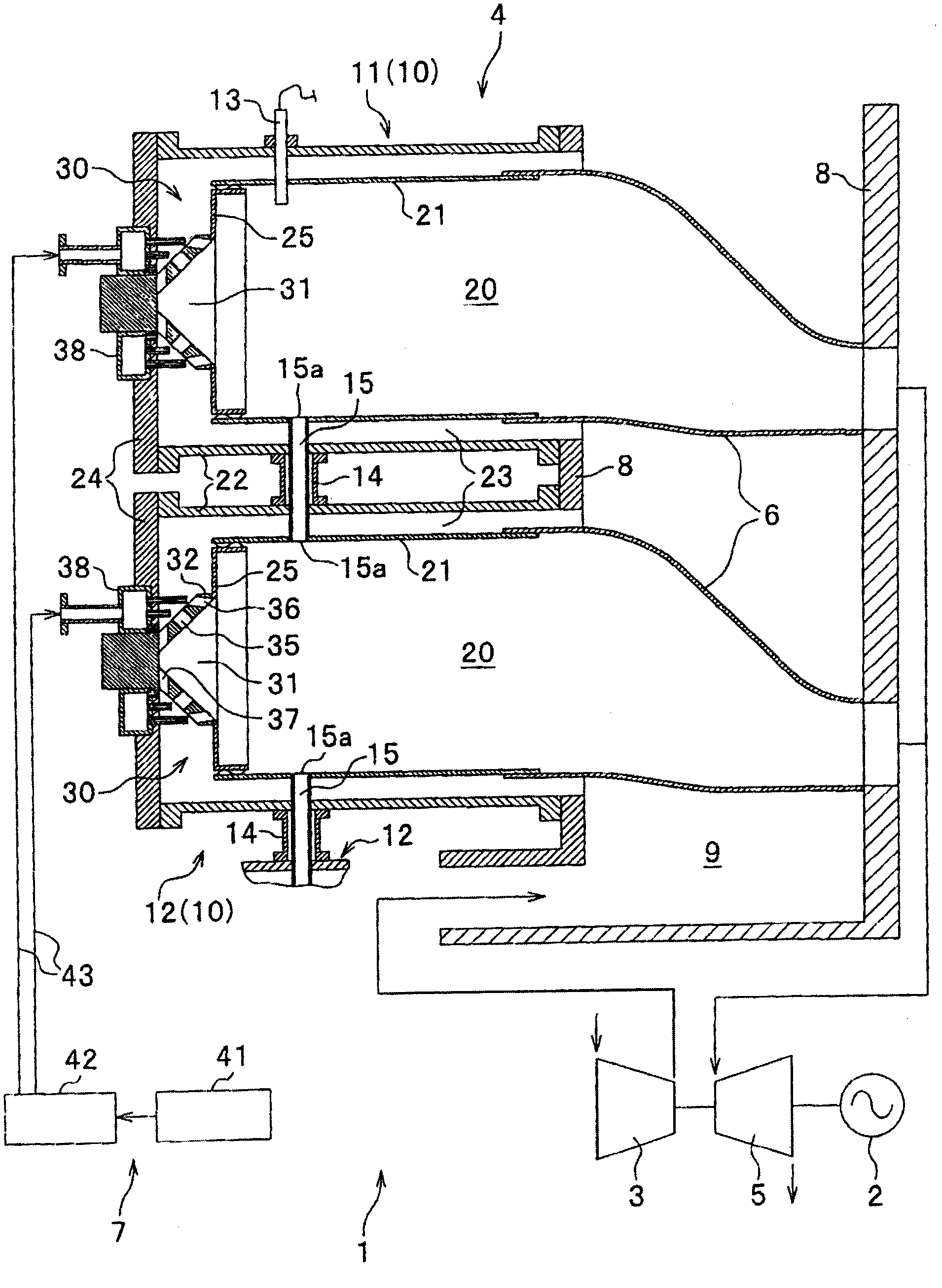
[0041] refer to figure 1 , the gas turbine facility including the gas turbine 1 is a gas turbine facility for power generation including the generator 2 to be driven by the gas turbine 1 .

[0042] The gas turbine 1 includes: a compressor 3 for compressing air; a gas turbine combustor 4 for combusting fuel to generate combustion gas by using combustion air which is a part of the compressed air obtained by the compressor 3; A turbine 5 that is driven to rotate by high-pressure combustion gas; a transition piece 6 that introduces the combustion gas from the gas turbine combustor 4 to the turbine 5; and a fuel supply system that supplies gas fuel (for example, liquefied natural gas) to the gas turbine combustor 4 7; and supports the casing 8 of the gas turbine combustor 4 while forming the casing 9 in which the compressed air discharg...

Embodiment 2

[0085] refer to Figure 7 ~ Figure 9 Embodiment 2 of the present invention will be described. In the second embodiment, a plurality of main burners 50 and 60 are arranged on the outer peripheral side of the burner 30, and the other structures are basically the same as those in the first embodiment.

[0086] In addition, in the second embodiment and the third and fourth embodiments described later, the description of the same parts as the first embodiment will be omitted or briefly described, and the differences will be emphasized in the description. In addition, the same symbols are used as necessary for the same or corresponding components as those of the first embodiment. In addition, Embodiments 2 to 4 have the same function and effect as Embodiment 1.

[0087] And, in embodiments two to four, the mixing chamber wall, the mixing chamber 31 and the fuel nozzle are respectively the central mixing wall, the central mixing chamber and the central fuel nozzle, and the mixing c...

Embodiment 3

[0111] refer to Figure 10 ~ Figure 12 Embodiment 3 of the present invention will be described.

[0112] refer to Figure 10 and Figure 11 The burners 70 and 80 of the burner 10 included in the gas turbine combustor 4 of the third embodiment are constituted by the pilot burner 70 corresponding to the burner 30 of the second embodiment, and the main burner 80 .

[0113] The pilot nozzle 70 has a mixing chamber wall 72 forming a conical mixing chamber 71 opened toward the downstream in the axial direction, and a fuel nozzle 79 as a center nozzle for supplying fuel. The mixing chamber wall surface 73 of the mixing chamber wall 72 is formed in a conical shape, and forms the conical mixing chamber 71 .

[0114] In addition, on the mixing chamber wall 72, a plurality of air introduction holes 75 and 76 for introducing combustion air, or introducing combustion air and fuel together into the mixing chamber 71 are arranged in the axial direction in first and second rows R1 and It ...


PUM


Abstract

The invention provides a gas turbine combustor. In the gas turbine combustor, the reduction of NOx generated by premixed combustion is achieved by promoting the air introduction passage provided on the mixing chamber wall of the burner and the mixing of fuel and air in the mixing chamber, while achieving ignition characteristics and flame propagation Enhanced features. A gas turbine combustor includes a plurality of burners (10), spark plugs (13), and flame propagation tubes (15) that spread flames between the burners. Each burner has a mixing chamber wall (32) forming a mixing chamber (31), and a burner (30) having a fuel nozzle. A plurality of air introduction holes (35, 36) for introducing combustion air into the mixing chamber together with fuel from fuel nozzles are provided on the mixing chamber wall (32). Combustion air and fuel ejected from the air inlet hole (35) into the mixing chamber become a mixed gas (m1, m2) and are directed to the spark plug and the flame propagation tube.

Description

technical field [0001] The present invention relates to a gas turbine combustor comprising a plurality of combustors for supplying combustion gas generated by combusting a mixture of fuel and air to the gas turbine, a spark plug, and a flame propagation tube for propagating flames between the combustors. Background technique [0002] As a gas turbine combustor included in a gas turbine commonly used in the past, there is known a gas turbine combustor equipped with a plurality of can-type combustors, each of which is configured to react fuel and compressed air to generate gas for rotationally driving the turbine. Combustion gas of high temperature and high pressure (for example, refer to Patent Document 1). [0003] These plurality of combustors are arranged on a circle along the circumferential direction of the turbine rotor, and the combustors adjacent to each other in the circumferential direction are connected by connecting pipes, and flame propagation pipes are provided ...

Claims


Application Information

Patent Timeline
Patent Type & Authority Patents(China)
IPC IPC(8): F23D14/02F23D14/64F23D14/58
CPCF23D2207/00F23R3/343F23R3/286F23R3/48
Inventor 平田义隆吉田正平关口达也林明典
Owner MITSUBISHI POWER LTD
Learn More