
Signal transformation circuit and digital signal display device

A signal conversion and digital technology, applied in the field of signal conversion, can solve the problems of data loss and video signal being susceptible to interference, and achieve the effect of avoiding data loss and enhancing anti-interference ability.

Inactive Publication Date: 2012-03-21
CHINA GREATWALL TECH GRP CO LTD
View PDF5 Cites 14 Cited by
  • Summary
  • Abstract
  • Description
  • Claims
  • Application Information

AI Technical Summary

Problems solved by technology

[0003] The purpose of the embodiment of the present invention is to provide a signal conversion circuit, aiming at solving the problems that video signals are susceptible to interference and data may be lost at the present stage

Method used


Image

  • Signal transformation circuit and digital signal display device
  • Signal transformation circuit and digital signal display device
  • Signal transformation circuit and digital signal display device

Examples


Embodiment 1

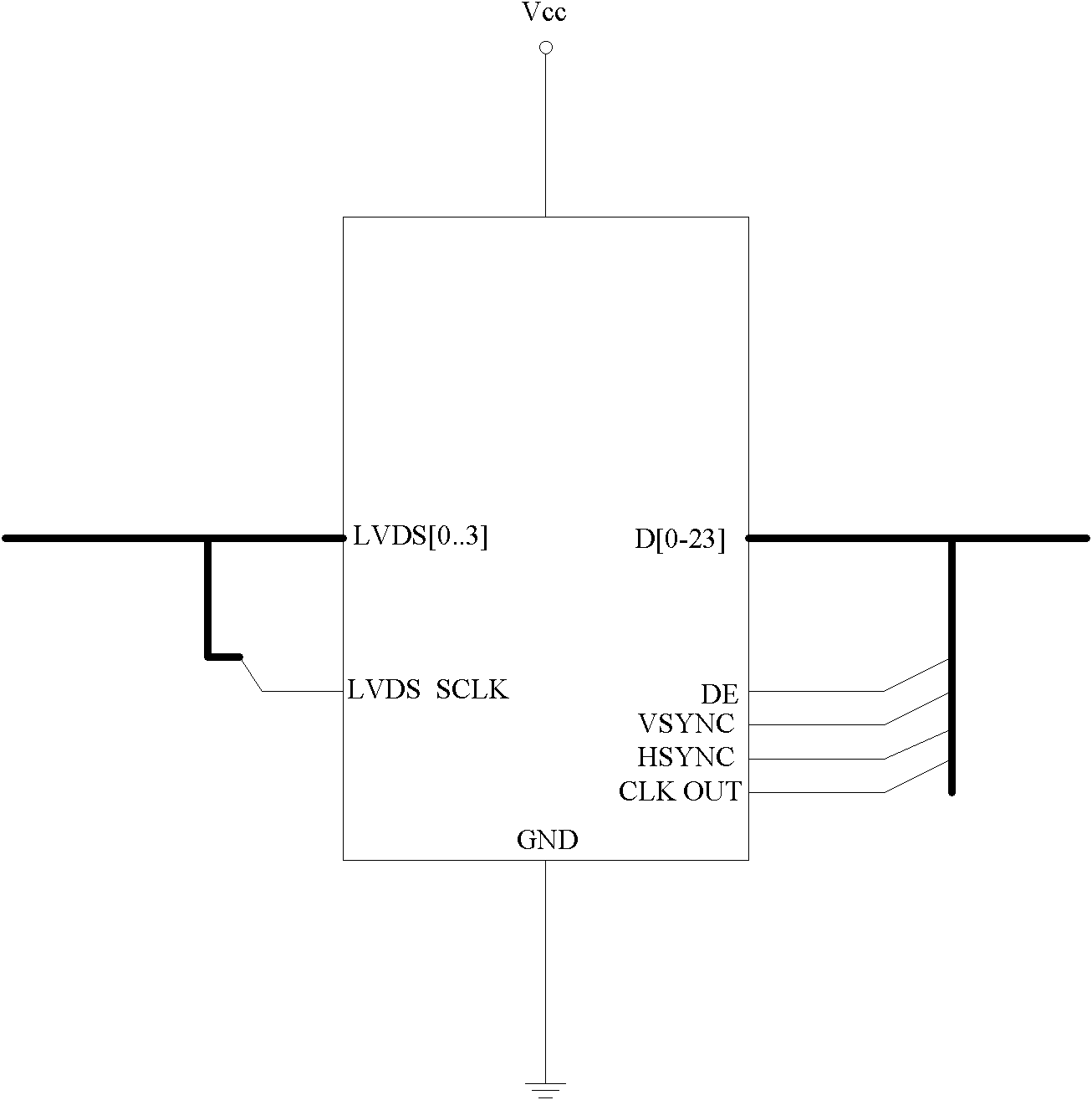
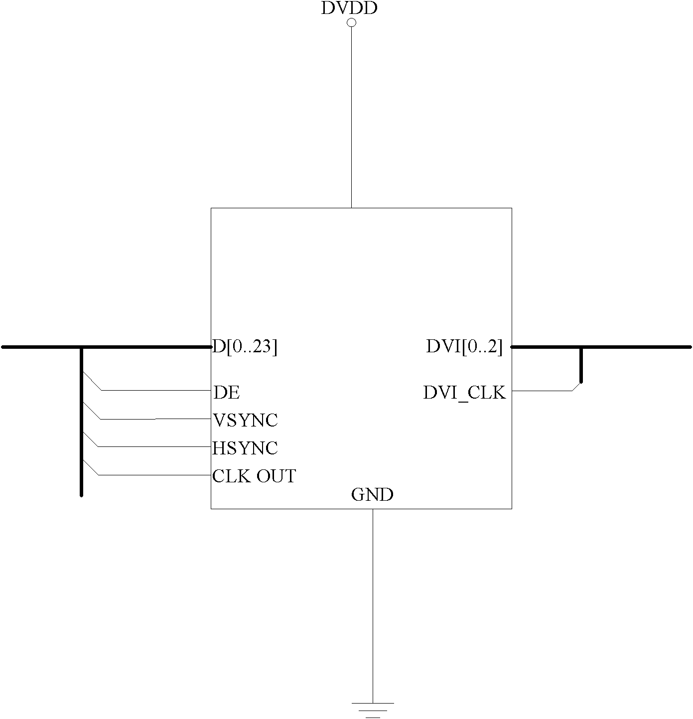
[0028] figure 1 The circuit structure of the signal conversion circuit provided by the embodiment of the present invention is shown, and only the parts related to the embodiment of the present invention are shown for convenience of description.

[0029] The digital LVDS video signal decoding chip 11 is used to convert the digital LVDS video signal into a digital RGB24bit universal video bus signal.

[0030] The bus terminal 12 is connected with the digital LVDS video signal decoding chip 11, and is used to enhance the anti-interference ability of the digital RGB24bit universal video bus signal.

[0031] The digital DVI video signal encoding chip 13 is connected with the bus terminal 12, and is used for encoding the digital RGB24bit universal video bus signal with enhanced anti-interference ability into a digital DVI video signal.

[0032] In the embodiment of the present invention, the structure of the digital LVDS video signal decoding chip 11 is as follows figure 2 As sho...

Embodiment 2

[0037] As an embodiment of the present invention, an ESD (Electro-Static discharge, electrostatic discharge) protection circuit 14 is added in the circuit in the above-mentioned embodiment, as a branch, with the digital DVI video signal encoding chip 13 in the above-mentioned embodiment and DVI video signal output ports are connected separately, such as Figure 4 As shown, it is used to protect the digital DVI video signal from overvoltage.

Embodiment 3

[0039] The signal conversion circuit provided in the embodiment of the present invention can be used in bank ATM cash machines, and can also be used in digital signal display devices such as industrial control display devices.

[0040] The embodiment of the present invention converts the digital LVDS video signal into a digital DVI video signal and then transmits it to the display terminal, which enhances the anti-interference ability of the output signal and avoids data loss during the conversion process from digital signal to analog signal.


PUM


Abstract

The invention is applicable to the field of digital signal transformation and provides a signal transformation circuit and a digital signal display device. The circuit comprises a digital LVDS (Low Voltage Differential Signaling) video signal decoding chip, a bus termination and a digital DVI (Digital Video Interactive) video signal encoding chip, wherein the digital LVDS video signal decoding chip is used for transforming LVDS video signals into RGB 24 bit universal video bus signals; the bus termination joint is connected with the digital LVDS video signal decoding chip and is used for enhancing the anti-interference capacity of the digital RGB 24 bit universal video bus signals; and the digital DVI video signal encoding chip is connected with the bus termination joint and used for encoding the digital RGB 24 bit universal video bus signals with enhanced anti-interference capacity into digital DVI video signals. In the invention, the LVDS video signals are transformed into the digital DVI video signals and then are transmitted to a display terminal, so that the anti-interference capacity of the output signals is enhanced, and data loss during the transforming process of the digital signals to analog signals can be avoided.

Description

technical field [0001] The invention belongs to the field of signal conversion, in particular to a signal conversion circuit and a digital signal display device. Background technique [0002] In the fields of industrial control and financial ATM cash machines, etc., the dual-screen display function is displayed. Usually, the computer processor processes the information into an RGB24bit general video bus signal, and converts the signal format into an analog VGA (Video Graphics Array, video image array) video signal. , to display terminal output externally. However, based on the nature of the analog VGA video signal, in the environment of industrial control and public places, the signal is susceptible to interference, which is likely to cause image shaking, ripples, etc., and even cause data loss when the digital signal is converted to an analog signal. Contents of the invention [0003] The purpose of the embodiments of the present invention is to provide a signal conversi...

Claims


Application Information

Patent Timeline
Patent Type & Authority Applications(China)
IPC IPC(8): G09G5/00H04N7/26
Inventor 周峰
Owner CHINA GREATWALL TECH GRP CO LTD
Learn More