
Vacuum assist syringe filling

A syringe and vacuum source technology, which is applied in the field of the system for removing air from the tube group, can solve the problem that the contrast agent cannot be used for another injection and wastes.

Inactive Publication Date: 2012-03-21
马林克罗特有限责任公司
View PDF7 Cites 9 Cited by
  • Summary
  • Abstract
  • Description
  • Claims
  • Application Information

AI Technical Summary

Problems solved by technology

Any contrast medium left in the syringe after a single injection cannot be used for another injection and is thus wasted

Method used


Image

  • Vacuum assist syringe filling
  • Vacuum assist syringe filling
  • Vacuum assist syringe filling

Examples


Embodiment Construction

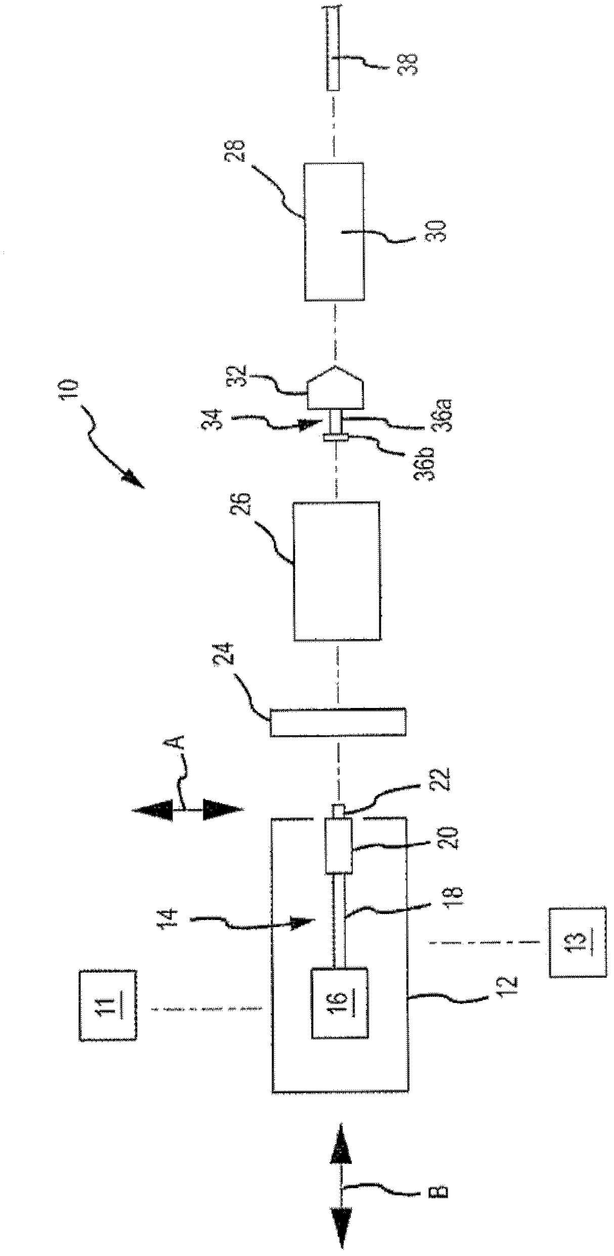
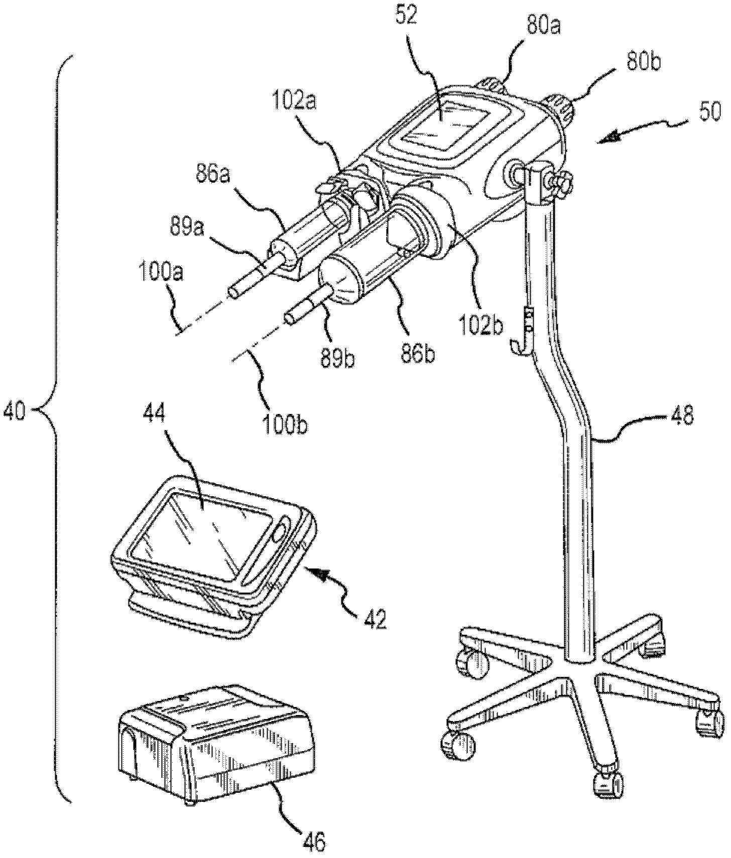
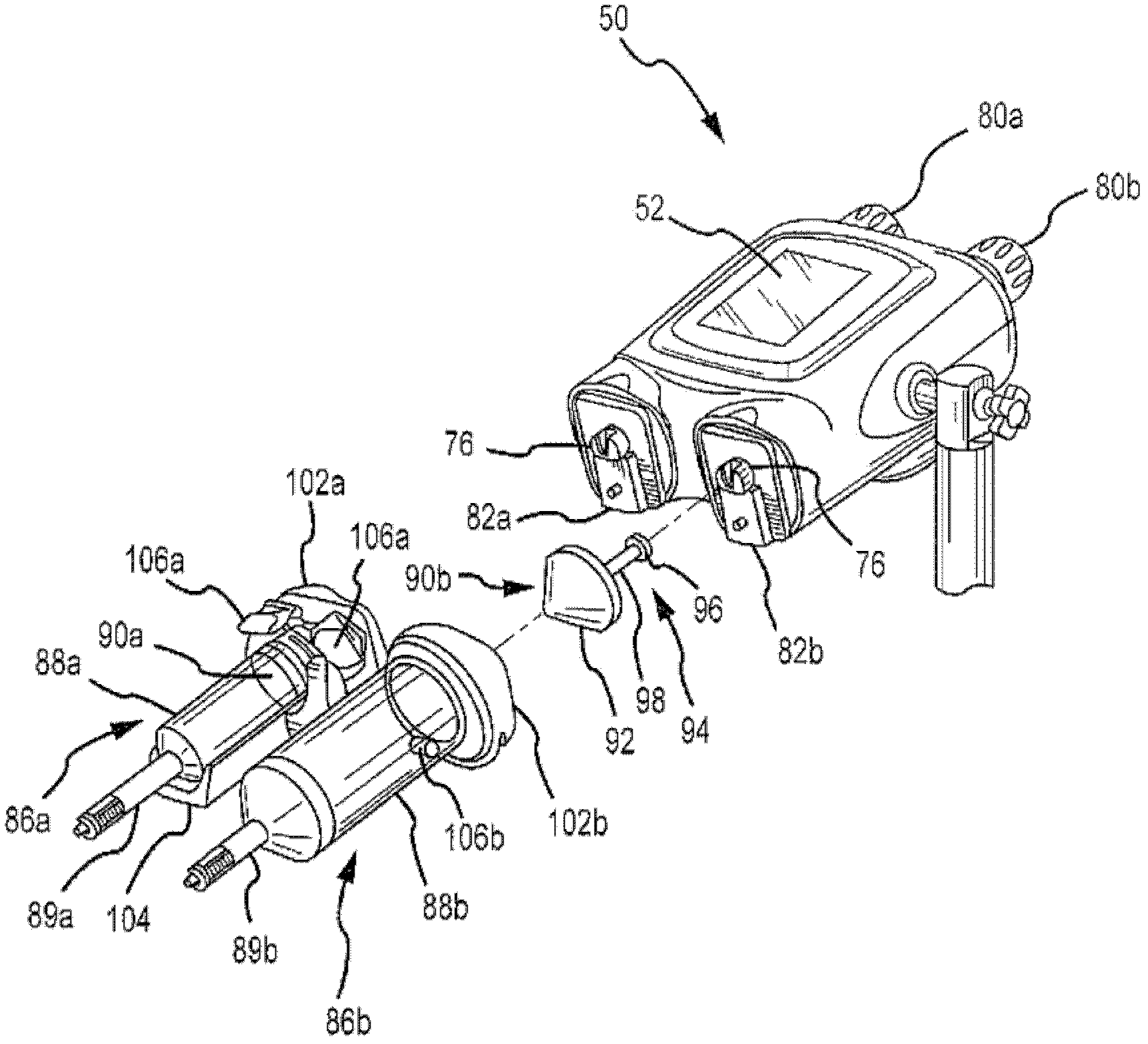
[0050] figure 1 A schematic diagram of one embodiment of an injection device in the form of a power injector 10 with a power head 12 is shown. One or more graphical user interfaces or GUI 11 may be associated with the power head 12. Each GUI 11: 1) can have any suitable size, shape, structure, and / or type; 2) can be operably interconnected with the power head 12 in any suitable manner; 3) can be arranged in any suitable position; 4) It can be configured to provide one or any combination of the following functions: control one or more aspects of the operation of the power injector 10; enter / edit one or more parameters associated with the operation of the power injector 10; and display appropriate information (For example, information associated with the operation of the power injector 10); or 5) a combination of the foregoing. Any suitable number of GUI 11 can be utilized. In one embodiment, the power injector 10 includes a GUI 11 integrated by a console that is isolated from ...


PUM


Abstract

A multi-dose injection system (108) is disclosed that allows for vacuum-assisted removal of air from an interconnected tubing set (110) and syringes (126, 127) and subsequent filling with fluid. The injection system (108) may include a bulk fluid container holder module (116) operable to hold one or more bottles (118, 120) of fluid for administration to a patient. The holder module (116) may include a vacuum source (240) that is selectively fluidly interconnectable to the tubing set (110). Air may be removed from the tubing set (110) and syringes (126, 127) by fluidly interconnecting the vacuum source (240) to the tubing set (110). Then the vacuum source (240) may be fluidly isolated from the tubing set (110) and the bottles (118, 120) fluidly interconnected to the tubing set (110), thereby allowing fluid from the bottles (118, 120) to fill the at least partially evacuated tubing set (110) and syringes (126, 127).

Description

Technical field [0001] The present invention relates generally to power injectors, and more specifically to systems and methods for removing air from power injectors and related tubing sets. Background technique [0002] Many medical procedures require the injection of one or more medical fluids into the patient. For example, medical imaging processing usually involves injection of a contrast agent into the patient. The contrast agent can also be injected into the patient together with saline or other fluids. Other medical treatments involve the injection of one or more fluids into the patient for therapeutic purposes. Power injectors can be used for these types of applications. [0003] Power injectors generally include components commonly referred to as powerheads. One or more syringes can be installed to the power head in a variety of ways (for example, a detachable way; a back-loading way; a front-loading way; a side-loading way). Each syringe typically includes characteris...

Claims


Application Information

Patent Timeline
Patent Type & Authority Applications(China)
IPC IPC(8): A61M5/145A61J1/00A61M5/00A61M5/178B65B3/00B65B31/04
CPCA61M2005/1402A61M5/445A61M5/007A61M2209/045A61M5/19A61M2205/3653A61M2005/3114A61M5/14546A61M2005/3128A61M2005/14553A61M2205/12
Inventor C.S.尼尔
Owner 马林克罗特有限责任公司
Learn More