
Ultra-high pressure device based on hinged-type hexahedral press

A hexahedral, ultra-high pressure technology, applied in the process of applying ultra-high pressure and other directions, to achieve the effects of superior overall performance, increased service life, and quick installation and debugging

Inactive Publication Date: 2012-03-28
JILIN UNIV
View PDF6 Cites 7 Cited by
  • Summary
  • Abstract
  • Description
  • Claims
  • Application Information

AI Technical Summary

Problems solved by technology

[0005] The technical problem to be solved by the present invention is aimed at the deficiencies in the existing high-pressure technology for generating large-cavity static high-voltage devices, and aims to provide a pressure conversion efficiency higher, low cost, high efficiency and low energy consumption, easy to install and debug. Easier maintenance work, new device for generating ultra-high hydrostatic pressure in large chambers

Method used


Image

  • Ultra-high pressure device based on hinged-type hexahedral press
  • Ultra-high pressure device based on hinged-type hexahedral press
  • Ultra-high pressure device based on hinged-type hexahedral press

Examples


Embodiment 1

[0023] Embodiment 1 Illustrates the structure of the present invention in conjunction with the accompanying drawings

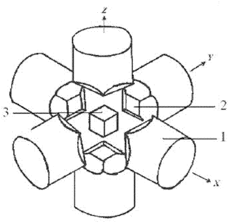
[0024] The novel device for generating static high pressure of the present invention is based on the hexahedron press frame of hinged frame (its structure is as follows: figure 1 Shown) hexahedral large cavity static high pressure device.

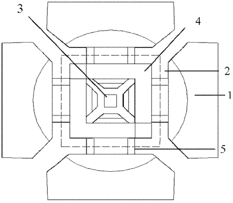
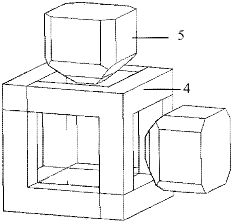
[0025] The plane schematic diagram of the ultra-high pressure device based on the hinged hexahedron press of the present invention is as follows figure 2 shown. exist figure 1 , 2 Among them, 1 is the anvil of the press, which is a cemented carbide anvil driven by the hydraulic pressure of the hexahedron press, and there are six in total; 2 is the anvil surface of the anvil of the press; 3 is a synthetic block, which is in the shape of a cube and contains synthetic materials; 5 is a pressurized anvil, the shape of a kind of pressurized anvil 5 of the present invention can refer to Figure 6 , Figure 6 Its cross-sect...

Embodiment 2

[0027] Embodiment 2 Specific examples

[0028] 1. For example, WC is selected as the material of the hexahedral press anvil 1 (top hammer), and when the size of the anvil surface is 23.5*23.5mm, the side length of the bottom surface of the pressurized anvil 5 is selected to be 14.5*14.5mm. The side length of the small surface of the pressurized anvil 5 can be changed in the range of 1-4 mm, so that different sizes and pressures of the high-pressure synthesis chamber can be obtained. When the side length of the small surface of the pressurized anvil 3 is 3mm, the pressure of the high-pressure cavity can reach 23GPa;

[0029] At this time, the pressurized anvil bracket 6 is made of alloy steel, the cross-section of the three square columns is 4.5*4.5mm, the length of the two short square columns is 14.5mm, and the length of the other long square column is 19mm.

[0030] 2. For example, WC is selected as the material of the anvil 1 (top hammer) of the hexahedral press, and when th...


PUM


Abstract

The invention discloses an ultra-high pressure device based on a hinged-type hexahedral press and belongs to the technical field of ultra-hard material synthesis equipment. The ultra-high pressure device structurally comprises six press anvils (1) which are synchronously driven by a hexahedral press, a cubic synthesis block (3) and pressurization anvils (5) arranged between press anvil faces (2) and the plane of the synthesis block (3). The invention is characterized in that the ltra-high pressure device further comprises a cubic support frame (4) which is formed by assembly of four pressurization anvil holders (6), each pressurization anvil holder (6) is formed by three columns which are perpendicular to one another, and the pressurization anvils (5) can pass through the six planes of the cubic support frame (4) and move in the axial direction of the pressurization anvils (5) to apply a pressure to the synthesis block (3) or relieve the pressure of the synthesis block (3). The invention has the biggest advantage as follows: the six pressurization anvils (5) can be assembled on the cubic support frame (4) very easily and can be used directly without needing setting-up or alignment; the installation and set-up are rapid and accurate; and the time is saved.

Description

technical field [0001] The invention belongs to the technical field of superhard material synthesis equipment, in particular to a device for generating static high pressure used in a hinged hexahedron hydraulic press. Background technique: [0002] A high-temperature and high-pressure environment is a necessary condition for the development of artificially synthesized superhard materials such as diamond and cubic boron nitride (cBN), as well as related high-pressure scientific research. Large-cavity static high-pressure device is the main equipment for generating high-temperature and high-pressure environment. Among the polyhedral high-pressure devices, the hinged hexahedron press device has a hexahedron pressure chamber, which is compact in structure, relatively simple in processing and installation, and relatively cheap in cost. At present, this equipment has been widely used in the superhard material industry, and it is the main production equipment for my country to bec...

Claims


Application Information

Patent Timeline
IPC IPC(8): B01J3/06
Inventor 朱品文何志王欣陶强黎军军崔田刘冰冰
Owner JILIN UNIV
Learn More