Tin soldering device for commutator and armature wire

A commutator and armature technology, used in tin feeding devices, auxiliary devices, welding equipment, etc., can solve the problems of low welding efficiency, poor quality reliability, insulation damage, etc., and achieve the effect of high welding efficiency and good welding quality.

Inactive Publication Date: 2012-03-28
无锡先锋电机有限公司
View PDF0 Cites 17 Cited by
  • Summary
  • Abstract
  • Description
  • Claims
  • Application Information

AI Technical Summary

Problems solved by technology

[0002] At present, in the manufacturing process of DC motors, the connection between the armature wire of the rotor and the commutator is soldered to ensure its electrical conductivity. There are usually two methods, one is to use a high-power electric soldering iron with solder wire Fusion welding method; the other is the dip welding method in which the rising piece of the commutator is immersed in a molten tin basin for welding. The soldering iron fusion welding method has poor penetration performance, is prone to virtual welding, and the welding efficiency is also very low; the dip welding method The high temperature of the molten tin liquid is likely to cause insulation damage between the commutator segments, and tin oxides will also adhere to the surface. Generally speaking, the above two methods have poor quality and reliability, low welding efficiency and seriously affect the motor. Shortcomings in production quality and efficiency

Method used


Image

  • Tin soldering device for commutator and armature wire
  • Tin soldering device for commutator and armature wire
  • Tin soldering device for commutator and armature wire

Examples


Embodiment Construction

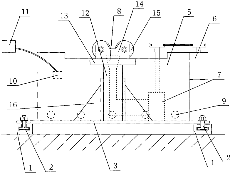
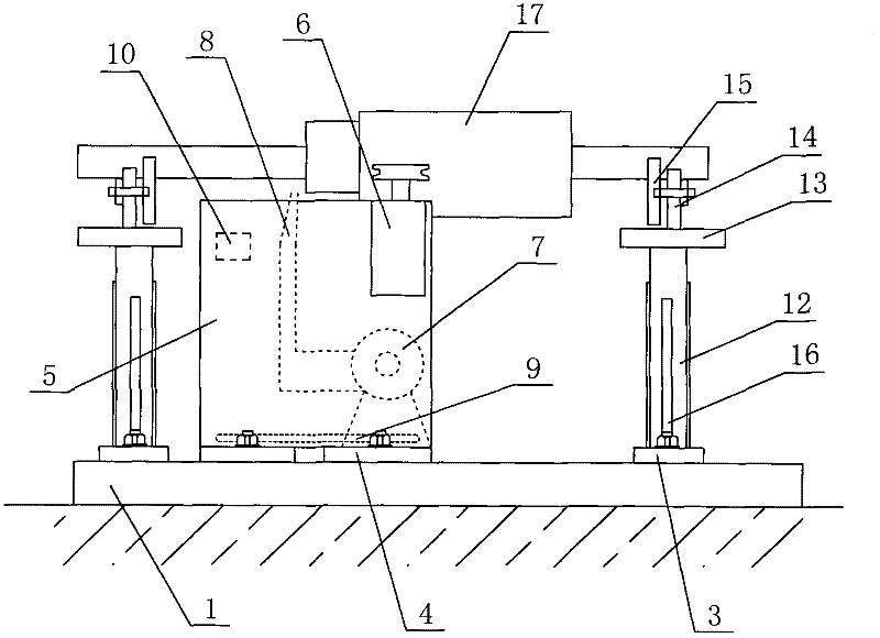
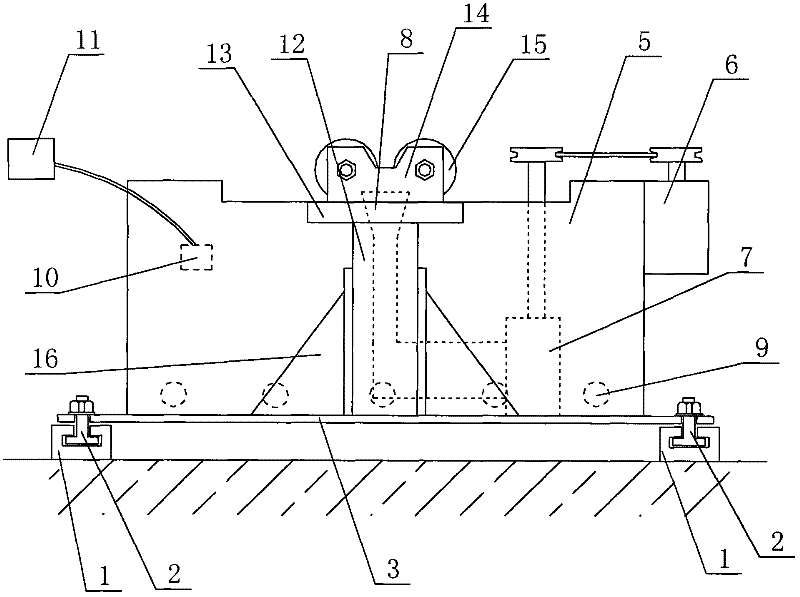
[0016] Please refer to Figure 1 to Figure 2 as shown, figure 1 It is a side view of the commutator and armature wire soldering device of the present invention; figure 2 It is a schematic diagram of the specific use of the commutator and armature wire soldering device of the present invention.

[0017] In this embodiment, a commutator and armature wire soldering device includes two supporting rails 1 arranged in parallel and at intervals, T-shaped grooves are opened on the supporting rails 1, and the tin basin 5 is arranged on the tin basin. On the bottom plate 4, the tin basin bottom plate 4 is installed on the support rail 1 by T-shaped bolts 2, and a support is installed on the support rail 1 on both sides of the tin basin 5, and the support is arranged on the support bottom plate 3 , the bracket bottom plate 3 is installed on the support rail 1 through T-shaped bolts 2, and the bracket includes a support rod 12 whose bottom is fixed on the bracket bottom plate 3, and th...


PUM


Abstract

The invention discloses a tin soldering device for a commutator and an armature wire, which is used for welding the commutator and the armature wire of a motor, and comprises a base, a tin basin and supports, wherein the tin basin is arranged on the base; the supports are arranged at both sides of the tin basin; one side of the tin basin is provided with a drive motor; the drive motor is connected with a tin spraying pump arranged in the tin basin; the tin spraying pump is communicated with a spray nozzle arranged in the tin basin; heating pipes are arranged in the tin basin; the inner wall of the tin basin is provided with a temperature sensor; and the temperature sensor is electrically connected with a controller. In the tin soldering device for the commutator and the armature wire, a motor rotor is arranged above rollers of the supports, so that the connected faces of the armature wire and the commutator on the motor rotor are just located above the spray nozzle in the tin basin; the drive motor is started to drive the tin spraying pump to spray molten tin onto the connected faces of the armature wire with the commutator, and simultaneously, the motor rotor is rotated to implement welding, thereby, not only is the welding efficiency high, but also the welding quality is good.

Description

technical field [0001] The invention relates to a motor auxiliary manufacturing equipment, in particular to a commutator and armature wire soldering device for welding the commutator and armature wire of a motor. Background technique [0002] At present, in the manufacturing process of DC motors, the connection between the armature wire of the rotor and the commutator is soldered to ensure its electrical conductivity. There are usually two methods, one is to use a high-power electric soldering iron with solder wire Fusion welding method; the other is the dip welding method in which the rising piece of the commutator is immersed in a molten tin basin for welding. The soldering iron fusion welding method has poor penetration performance, is prone to virtual welding, and the welding efficiency is also very low; the dip welding method The high temperature of the molten tin liquid is likely to cause insulation damage between the commutator segments, and tin oxides will also adher...

Claims


Application Information

Patent Timeline
Patent Type & Authority Applications(China)
IPC IPC(8): B23K3/00B23K3/06B23K3/08
Inventor 盛明学
Owner 无锡先锋电机有限公司
Why Eureka
Try Eureka