Torque coordination control method of hybrid electric vehicle engine and motor

A hybrid vehicle, motor torque technology, applied in hybrid vehicles, motor vehicles, transportation and packaging, etc., to achieve the effect of improving driving comfort and power, improving economy, and increasing response speed

Inactive Publication Date: 2012-03-28
CHONGQING CHANGAN AUTOMOBILE CO LTD +1
5 Cites 7 Cited by

AI-Extracted Technical Summary

Problems solved by technology

[0004] The purpose of the present invention is to provide a method for coordinatingly controlling the torque of the engine and the motor to meet the torque reduction requirements of the transmission during hybrid driving. By coordinatin...

Method used

[0046] 4) The HCU coordinates and controls the torque of the engine and the motor according to the current working state of the motor to achieve the purpose of torque reduction.
[0059] 4) The HCU coordinates and controls the torque of the engine and the motor according to the current working state of the motor to achieve the purpose of torque reduction.
[0072] 4) The HCU coordinates and controls the torque of the engine and the motor accord...

Abstract

The invention provides a method for coordination control of engine and motor torques to meet torque reducing requirement of a speed changer in hybrid driving process. The method reaches torque reducing purpose by coordination control of motor and engine torques, increases torque reducing response speed by fast response characteristic of the motor, benefits for adjustment of speed ratio and improves the driving comfortableness and dynamic property. Simultaneously, the invention preferentially reaches the torque reducing purpose by adjusting the motor, reduces dynamic process of the engine, facilitates the engine to work more stably and improves economical efficiency.

Application Domain

Hybrid vehicles

Technology Topic

VariatorElectric vehicle +7

Image

  • Torque coordination control method of hybrid electric vehicle engine and motor
  • Torque coordination control method of hybrid electric vehicle engine and motor
  • Torque coordination control method of hybrid electric vehicle engine and motor

Examples

  • Experimental program(1)

Example Embodiment

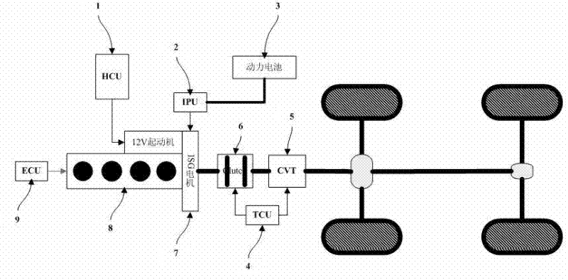
[0040] figure 1 Shown is a parallel hybrid power system, which includes vehicle controller HCU 1, ISG motor controller IPU2, power battery 3, transmission controller TCU4, continuously variable transmission CVT5, clutch 6, ISG motor 7 (hereinafter referred to as motor), engine 8 , engine controller ECU9.
[0041] The method of the present invention uses the vehicle controller HCU1 as a carrier, and is realized through a parallel hybrid power system including this control method. The following five different situations are combined. Figure 7 The technical implementation process of the present invention will be described.
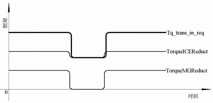
[0042]Motor assist case 1 (see figure 2 ):
[0043] 1) The vehicle drives to a certain state, the driver's demand torque Tq_drv_req=160Nm, Tq_boost=120Nm, Tq_drv_req> Tq_boost, needs the motor to assist, the vehicle controller HCU1 distributes the target torque to the engine as Tq_ice_req=120Nm, and distributes it to the motor target torque Tq_mg_req=40Nm, at this time, the transmission controller TCU4 judges that the torque of the transmission input shaft needs to be reduced, and sends the target value of torque reduction Tq_trans_in_req=100Nm to the HCU through CAN communication, and the effective flag of torque reduction demand Flag_tq_reduct=1;
[0044] 2) Assuming that the current output torque of the engine is Tq_ice_act=120Nm, the output torque of the motor is Tq_mg_act=40Nm, the torque of the transmission input shaft is Tq_tran_in_act, the torque of the transmission input shaft is equal to the sum of the engine output torque and the motor output torque, Tq_tran_in_act=Tq_ice_act+Tq_mg_act =120+40=160Nm;
[0045] 3) The torque value that needs to be reduced on the basis of the current torque output DeltaTorqueReduct = Tq_trans_in_req - Tq_tran_in_act=100-160=-60Nm, DeltaTorqueReduct<0 and Flag_tq_reduct=1, proceed to the following steps for torque reduction control;
[0046] 4) The HCU coordinates and controls the torque of the engine and the motor according to the current working state of the motor to achieve the purpose of torque reduction.
[0047] Set the target value TorqueMGReduct of the motor after torque reduction, the minimum operating torque of the motor is TorqueMGMin=-110Nm; the target value of the engine after torque reduction is TorqueICEReduct.
[0048] Because Tq_mg_act=40Nm >0, the current motor is working in booster mode, and the priority is to reduce the motor torque. The specific method is as follows:
[0049] |DeltaTorqueReduct|=|-60|=60Nm,
[0050] Tq_mg_act=40Nm,
[0051] So |DeltaTorqueReduct|>= Tq_mg_act,
[0052] So TorqueMGReduct = 0Nm, Flag_tq_mg_reduct=1,
[0053] TorqueICEReduct = Tq_trans_in_req=100Nm, Flag_tq_ice_reduct=1.
[0054]
[0055] Motor assist case 2 (see image 3 ):
[0056] 1) When the vehicle drives to a certain state, the driver's demand torque is equal to Tq_drv_req=130Nm, Tq_boost=110Nm, Tq_drv_req> Tq_boost, the motor is required to assist, and the vehicle controller HCU1 allocates the engine target torque Tq_ice_req=100Nm, which is allocated to the motor target torque Tq_mg_req=30Nm, at this time, the transmission controller TCU4 judges that the torque of the transmission input shaft needs to be reduced, and sends the target value of torque reduction Tq_trans_in_req=110Nm to the HCU through CAN communication, and the effective flag of torque reduction demand Flag_tq_reduct=1;
[0057] 2) Set the current output torque of the engine as Tq_ice_act=100Nm, the output torque of the motor as Tq_mg_act=30Nm, and the torque of the transmission input shaft as Tq_tran_in_act, which is equal to the sum of the output torque of the engine and the output torque of the motor, Tq_tran_in_act=Tq_ice_act+Tq_mg_act=100+30= 130Nm;
[0058] 3) The torque value that needs to be reduced on the basis of the current torque output DeltaTorqueReduct = Tq_trans_in_req - Tq_tran_in_act=110-130=-20Nm, DeltaTorqueReduct<0, and Flag_tq_reduct=1, proceed to the following steps for torque reduction control;
[0059] 4) The HCU coordinates and controls the torque of the engine and the motor according to the current working state of the motor to achieve the purpose of torque reduction.
[0060] Set the target value TorqueMGReduct of the motor after torque reduction, the minimum operating torque of the motor is TorqueMGMin=-110Nm; the target value of the engine after torque reduction is TorqueICEReduct.
[0061] Because Tq_mg_act=30Nm >0, the current motor is working in booster mode, and the motor torque should be reduced first. The specific method is as follows:
[0062] |DeltaTorqueReduct|=|-20|=20Nm,
[0063] Tq_mg_act=30Nm,
[0064] So |DeltaTorqueReduct|
[0065] So TorqueMGReduct = Tq_mg_req+ DeltaTorqueReduct=30-20=10Nm, Flag_tq_mg_reduct=1,
[0066] TorqueICEReduct = Tq_ice_req=100Nm, Flag_tq_mg_reduct=0.
[0067]
[0068] Motor charging case 1 (see Figure 4 ):
[0069] 1) The vehicle drives to a certain state, the driver's demand torque is equal to Tq_drv_req=80Nm, the battery state of charge SOC=40, SOC_charge=60, SOC
[0070] 2) Set the current output torque of the engine as Tq_ice_act=100Nm, the output torque of the motor as Tq_mg_act=-20Nm, and the torque of the transmission input shaft as Tq_tran_in_act, which is equal to the sum of the output torque of the engine and the output torque of the motor, Tq_tran_in_act=Tq_ice_act+Tq_mg_act=100-20 =80Nm;
[0071] 3) The torque value that needs to be reduced on the basis of the current torque output DeltaTorqueReduct = Tq_trans_in_req - Tq_tran_in_act=50-80=-30Nm, DeltaTorqueReduct<0, and Flag_tq_reduct=1, proceed to the following steps for torque reduction control;
[0072] 4) The HCU coordinates and controls the torque of the engine and the motor according to the current working state of the motor to achieve the purpose of torque reduction.
[0073] Set the target value TorqueMGReduct of the motor after torque reduction, the minimum operating torque of the motor is TorqueMGMin=-110Nm; the target value of the engine after torque reduction is TorqueICEReduct.
[0074] Because Tq_mg_act=-20Nm < 0, the current motor is working in the charging mode, and the priority is to increase the motor torque. The specific method is as follows:
[0075] DeltaTorqueReduct+ Tq_mg_act=-30-20=-50Nm,
[0076] TorqueMGMin=-110Nm,
[0077] So DeltaTorqueReduct + Tq_mg_act > TorqueMGMin,
[0078] So TorqueMGReduct = Tq_mg_req + DeltaTorqueReduct=-20-30=-50Nm,
[0079] Flag_tq_mg_reduct=1,
[0080] TorqueICEReduct = Tq_ice_req=100Nm, Flag_tq_ice_reduct=0.
[0081]
[0082] Motor charging case 2 (see Figure 5 ):
[0083] 1) The vehicle drives to a certain state, the driver's demand torque is equal to Tq_drv_req=80Nm, the battery state of charge SOC=40, SOC_charge=60, SOC
[0084] 2) Set the current output torque of the engine as Tq_ice_act=100Nm, the output torque of the motor as Tq_mg_act=-20Nm, and the torque of the transmission input shaft as Tq_tran_in_act, which is equal to the sum of the output torque of the engine and the output torque of the motor, Tq_tran_in_act=Tq_ice_act+Tq_mg_act=100-20 =80Nm;
[0085]3) The torque value that needs to be reduced on the basis of the current torque output DeltaTorqueReduct = Tq_trans_in_req - Tq_tran_in_act=20-80=-60Nm, DeltaTorqueReduct<0, and Flag_tq_reduct=1, proceed to the following steps for torque reduction control;
[0086] 4) The HCU coordinates and controls the torque of the engine and the motor according to the current working state of the motor to achieve the purpose of torque reduction.
[0087] Set the target value TorqueMGReduct of the motor after torque reduction, the minimum operating torque of the motor is TorqueMGMin=-50Nm; the target value of the engine after torque reduction is TorqueICEReduct.
[0088] Because Tq_mg_act=-20Nm < 0, the current motor is working in the charging mode, and the priority is to increase the motor torque. The specific method is as follows:
[0089] DeltaTorqueReduct+ Tq_mg_act=-60-20=-80Nm,
[0090] TorqueMGMin=-50Nm,
[0091] So DeltaTorqueReduct+ Tq_mg_act< TorqueMGMin,
[0092] So TorqueMGReduct = TorqueMGMin=-50Nm, Flag_tq_mg_reduct=1,
[0093] TorqueICEReduct = Tq_ice_req+DeltaTorqueReduct+ Tq_mg_req –TorqueMGMin
[0094] =100-60-20-(-50)=70Nm,
[0095] Flag_tq_ice_reduct=1.
[0096]
[0097] The engine works alone (see Image 6 ):
[0098] 1) The vehicle drives to a certain state, the driver's demand torque Tq_drv_req=80Nm, Tq_boost=110Nm, Tq_drv_req SOC_charge, also does not need The motor works in charging mode. The vehicle controller HCU1 assigns the engine target torque Tq_ice_req=80Nm, and the motor target torque Tq_mg_req=0Nm. At this time, the transmission controller TCU4 judges that the transmission input shaft torque needs to be reduced, and sends a torque reduction signal to the HCU through CAN communication. Target value Tq_trans_in_req=40Nm, torque reduction demand valid flag Flag_tq_reduct=1;
[0099] 2) Set the current output torque of the engine as Tq_ice_act=80Nm, the output torque of the motor as Tq_mg_act=0Nm, and the torque of the transmission input shaft as Tq_tran_in_act, which is equal to the sum of the output torque of the engine and the output torque of the motor, Tq_tran_in_act=Tq_ice_act+Tq_mg_act=80-0= 80Nm;
[0100] 3) The torque value that needs to be reduced on the basis of the current torque output DeltaTorqueReduct = Tq_trans_in_req - Tq_tran_in_act=40-80=-40Nm, DeltaTorqueReduct<0, and Flag_tq_reduct=1, proceed to the following steps for torque reduction control;
[0101] 4) The HCU coordinates and controls the torque of the engine and the motor according to the current working state of the motor to achieve the purpose of torque reduction.
[0102] Set the target value TorqueMGReduct of the motor after torque reduction, the minimum operating torque of the motor is TorqueMGMin=-50Nm; the target value of the engine after torque reduction is TorqueICEReduct.
[0103] Because Tq_mg_act=0, the current motor is not working, and the engine drives the vehicle alone. The specific method is as follows:
[0104] TorqueMGReduct=0, Flag_tq_mg_reduct=0,
[0105] TorqueICEReduct = Tq_trans_in_req=40Nm, Flag_tq_ice_reduct=1.

PUM

no PUM

Description & Claims & Application Information

We can also present the details of the Description, Claims and Application information to help users get a comprehensive understanding of the technical details of the patent, such as background art, summary of invention, brief description of drawings, description of embodiments, and other original content. On the other hand, users can also determine the specific scope of protection of the technology through the list of claims; as well as understand the changes in the life cycle of the technology with the presentation of the patent timeline. Login to view more.

Similar technology patents

Client terminal for performing hybrid machine vision and method thereof

ActiveUS20200151482A1reduce load imposeimprove response speed
Owner:IPIXEL CO LTD

Display device, barrier device, and method of driving display device

InactiveCN102610202AImprove response speed
Owner:SONY CORP

Camera module and imaging apparatus

InactiveUS20110236009A1improve response speed
Owner:SONY CORP

Automatic winding control system for wide lead tape production line

InactiveCN103043482AImprove response speedQuality assurance
Owner:JIANGSU SANHUAN IND HLDG CO LTD

Classification and recommendation of technical efficacy words

  • Improve response speed

Liquid crystal display and liquid crystal drive circuit

InactiveUS20080309601A1improve response speed
Owner:SONY CORP

Liquid crystal display and manufacturing method thereof

ActiveUS20120300148A1reduce distortionimprove response speed
Owner:SAMSUNG DISPLAY CO LTD

Fast transient response circuit applied to LDO

PendingCN109116905AIncreased bandwidth and slew rateImprove response speed
Owner:拓尔微电子股份有限公司

RFID interrogator

InactiveUS20090009292A1reduce transient changeimprove response speed
Owner:CAMBRIDGE RESONANT TECH

Camera module and imaging apparatus

InactiveUS20110236009A1improve response speed
Owner:SONY CORP
Why Eureka
Try Eureka