Vibrating-type seam pressing and jointing integral machine for cement concrete pavement
A cement concrete and vibratory technology, applied to roads, roads, pavement details, etc., can solve problems such as difficulty in ensuring construction quality, achieve the effect of ensuring construction quality and improving work efficiency
- Summary
- Abstract
- Description
- Claims
- Application Information
AI Technical Summary
Problems solved by technology
Method used
Image
Examples
specific Embodiment approach 1
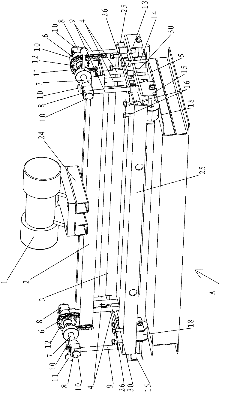
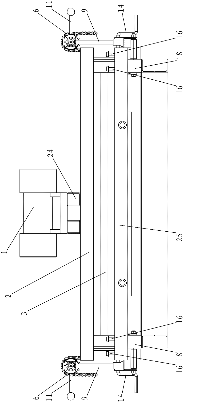
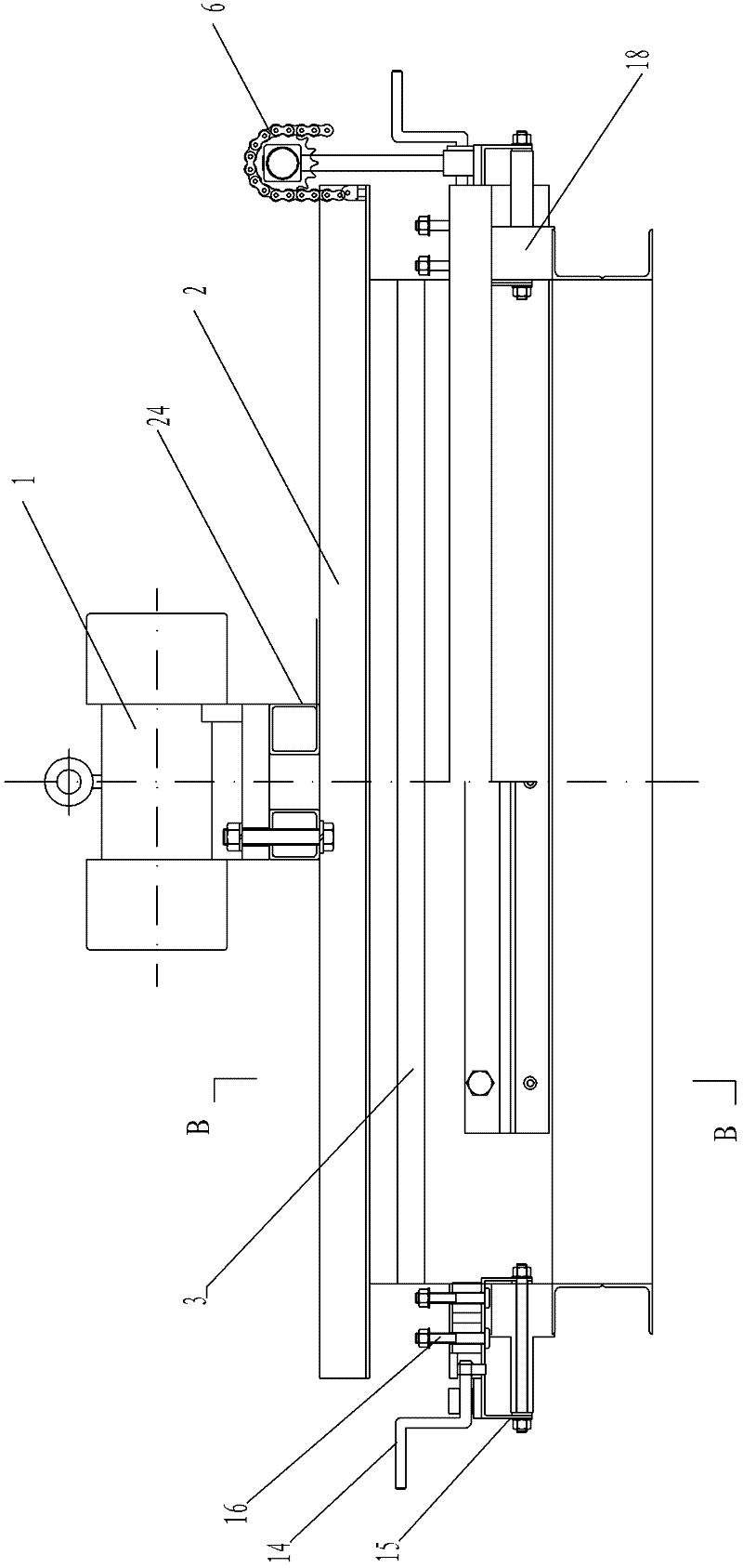
[0009] Specific implementation mode one: combine Figure 1 to Figure 5 Describe this embodiment, the cement concrete pavement vibratory caulking all-in-one machine in this embodiment includes a vibration motor 1, a knife holder 2, a blade 3, four vibration columns 4, a U-shaped main load-bearing plate bottom plate 5, and a load-bearing caulking plate support Frame 19, caulking plate pressing plate 20, thrust spring 21, spring bracket 22, first caulking plate guard plate 23, vibration beam bracket 24, second caulking protection plate 27, push screw 29, two chains 6, two A horizontal bar 7, four vibration position adjustment seats 8, four load-bearing pillars 9, a plurality of locking screws 10, two handles 11, two sprockets 12, two lower backing plates 13, two crank handles 14, Four roller brackets 15, a plurality of supporting screws 16, four rollers 18, two main bearing plate side plates 25, two connecting horizontal plates 26 and two cams 30;
[0010] The vibrating motor 1 ...
specific Embodiment approach 2
[0011] Specific implementation mode two: combination Figure 4 To illustrate this embodiment, the cement concrete pavement vibratory joint sealing machine of this embodiment also includes a plurality of damping rubber blocks 17, and each support screw 16 is fitted with a vibration damping rubber block 17, and the vibration damping rubber blocks 17 It is located between the roller bracket 15 and the side plate 25 of the main bearing plate. Such setting can reduce the vibration and reduce the noise during the operation of the machine. Other compositions and connections are the same as in the first embodiment.
specific Embodiment approach 3
[0012] Specific implementation mode three: combination Figure 5 The present embodiment will be described. In the present embodiment, the width W1 of the cutting edge portion of the blade 3 is smaller than the width W2 of the blade root portion. Such arrangement increases the strength of the blade. Other compositions and connections are the same as those in Embodiment 1 or Embodiment 2.
[0013] Working principle: Push the cement concrete pavement vibratory pressure joint filling machine to the position where the cement concrete pavement needs to be jointed, and put down the crank handle 14 that was in the lifting position beforehand, so that the U-shaped main load-bearing plate bottom plate 5 and its upper The member is lowered to meet the road surface, thereby securing the unit. Open the locking screw 10, start the switch of the vibration motor 1, and under the vibration of the vibration motor 1, the knife rest 2 and the blade 3 will vertically fall along the vibration col...
PUM
 Abstract
Description
Claims
Application Information
 - R&D
- Intellectual Property
- Life Sciences
- Materials
- Tech Scout
- Unparalleled Data Quality
- Higher Quality Content
- 60% Fewer Hallucinations
Browse by: Latest US Patents, China's latest patents, Technical Efficacy Thesaurus, Application Domain, Technology Topic, Popular Technical Reports.
© 2025 PatSnap. All rights reserved.Legal|Privacy policy|Modern Slavery Act Transparency Statement|Sitemap|About US| Contact US: help@patsnap.com


