Pile foundation static loading test device

A technology of static load test and pile foundation, which is applied in the test of foundation structure, foundation structure engineering, construction, etc., to achieve the effect of reducing the size of steel beams, simple assembly and disassembly, and fast construction operation

Inactive Publication Date: 2012-03-28
ZHEJIANG BAOYE CONSTR GROUP CO LTD
View PDF4 Cites 2 Cited by
  • Summary
  • Abstract
  • Description
  • Claims
  • Application Information

AI Technical Summary

Problems solved by technology

[0005] The purpose of the present invention is to provide a pile foundation static load test device for the deficiencies of the prior art. In order to solve the problem of collapse of objects, the structure has also been optimized to reduce the size of the steel beams of the reaction force device. The assembly is convenient and fast, the applicability is greater, the construction operation is faster, and no waste is generated during the test process, which is energy-saving and environmentally friendly. , low test cost

Method used


Image

  • Pile foundation static loading test device
  • Pile foundation static loading test device
  • Pile foundation static loading test device

Examples


Embodiment

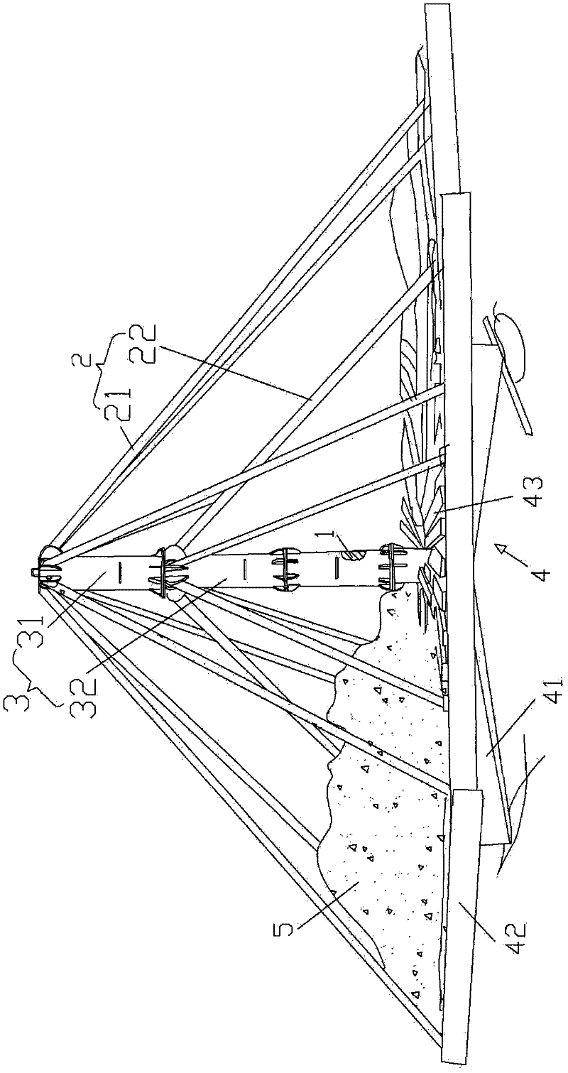
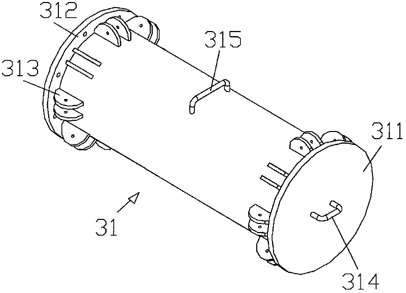
[0024] Example: see Figure 1 to 4 As shown, a pile foundation static load test device includes a pile to be tested 1, a connecting rod 2. The top rod 3 is composed of a foundation section top rod 31 and a connecting section top rod 32, and the foundation section top rod 31 is a top In the cylinder of the cover 311, a base section flange 312 is formed at the lower part of the base section ejector rod 31; the connecting section ejector rod 32 is a hollow cylinder and a connecting section flange 321 is formed at both ends. The base section flange 312 is connected to The joint half plates 321 are fixed together by bolts, the connecting joint flanges 321 of the two connecting joint jacks 32 are fixed together by bolts, the foundation section jack 31 and the connecting section jack 32 are sleeved on the pile 1 to be tested;

[0025] The connecting rod 2 consists of an outer ring connecting rod 21 and an inner ring connecting rod 22. One end of the outer ring connecting rod 21 is hinge...


PUM


Abstract

The invention discloses a pile foundation static loading test device. The device is characterized in that an ejector rod is composed of a base section ejector rod and linkage section ejector rods, the base section ejector rod is a cylinder with a base section head cover, and the lower part of the base section ejector rod is provided with a base section flange plate; the linkage section ejector rods are hollow cylinders and the two ends of the linkage section ejector rod are provided with linkage section flange plates, and the base section flange plate and the linkage section flange plates are fixed together through a bolt; the linkage section flange plates of two linkage section ejector rods are fixed together through the bolt, and the base section ejector rod and linkage section ejector rods are sleeved on a pile to be tested; a connecting rod is composed of an outer ring connecting rod and an inner ring connecting rod, one end of the outer ring connecting rod is articulated on the base section ejector rod, and the other end of the outer ring connecting rod is articulated on a soil-bearing base; and one end of the inner ring connecting rod is articulated on the linkage section ejector rods, and the other end of the inner ring connecting rod is articulated on the soil-bearing base. The test device provided by the invention has the advantages that steel beam size of a counterforce device is decreased, the assembling is convenient and rapid, the applicability is larger, the construction operation is more rapid, the waste is not generated in a testing process, thus the device is energy-saving, is environmentally-friendly, and the experimental cost is low.

Description

Technical field: [0001] The invention relates to the field of construction technology, and more specifically to equipment for carrying out static load tests of pile foundations in the field of construction. It is used for pile-loading counterweights during static load tests such as prestressed pipe piles, sinking pipe piles, bored piles, etc. . Background technique: [0002] In the pile foundation static load test, the reaction force between the action and the upper part of the pile is provided by the reaction force device. The ease of use of the reaction force device not only affects the cost of the pile foundation static load test, but also affects the results of the pile foundation static load test. ; At present, the pile foundation static load test reaction device is commonly used for pile-load reaction beam device and anchor pile reaction beam device. [0003] The anchor pile reaction beam device generally requires a suitable pile position arrangement around the test pile. If...

Claims


Application Information

Patent Timeline
Patent Type & Authority Applications(China)
IPC IPC(8): E02D33/00
Inventor 孙永明杜志强俞国方倪华君王光梅
Owner ZHEJIANG BAOYE CONSTR GROUP CO LTD
Why Eureka
Try Eureka