Pressure container

A technology for pressure vessels and plastic containers, which is applied in the direction of pressure vessels, container filling methods, and the outer wall of container structures, which can solve the problems of reducing the sealing effect and achieve the effect of preventing radial movement

Active Publication Date: 2012-03-28
MAGNA STEYR FAHRZEUGTECHN
View PDF10 Cites 22 Cited by
  • Summary
  • Abstract
  • Description
  • Claims
  • Application Information

AI Technical Summary

Problems solved by technology

Manufacture of such threads on plastic container cores leads to material build-up and thus to machining-induced depressions in this area
If the O-ring is arranged in this area, the sealing effect is thus reduced

Method used


Image

  • Pressure container
  • Pressure container
  • Pressure container

Examples


Embodiment Construction

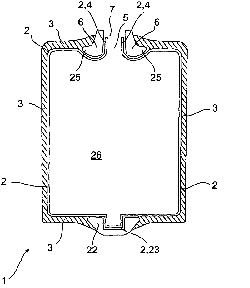
[0032] figure 1 The pressure vessel 1 shown is intended to contain a fluid under pressure, ie a liquid or a gas. The pressure vessel 1 has a plastic vessel core 2 or liner 2 which is produced from plastic, for example by means of blow molding or rotational sintering. The plastic container core 2 is surrounded by a support sleeve 3 . The support sleeve 3 is a fiber winding wound externally on the plastic container core 2 . For example the winding consists of reinforcing fibers such as carbon, aramid fibers, glass fibers, boron fibers, Al 2 o 3Fibers or their mixtures (hybrid filaments), which are embedded in a matrix of thermosetting plastics such as epoxy or phenolic resins or in thermoplastics such as PA12, PA6, PP. The support sleeve 3 thus consists of fibers and matrix and can absorb the pressure acting on the plastic container core 2 , which occurs because the fluid in the plastic container core 2 is stored under pressure. The fluid is thus stored or stored within the...


PUM


Abstract

In the case of a pressure container comprising a plastic container core (2) for storing a fluid under pressure, a support sheath (3) surrounding the plastic container core (2), a connection piece (4) formed at the plastic container core (2) and having an opening (5) for filling in and discharging the fluid from the plastic container core (2), a connection body (6) arranged radially outside the connection piece (4) and having a bore (7), a valve body (8) having a fluid duct (9) for conducting the fluid in and out through the opening (5) in the connection piece (4), wherein the valve body (8) is arranged in the opening (5) of the connection piece (4) and in the bore (7) of the connection body (6), preferably at least one annular groove (10) formed radially outside in the valve body (8), one first seal (11) being arranged in each of the at least one radially outside annular groove (10), so that the at least one first seal (11) rests radially inside on the connection piece (4), the valve body (8) is to be attached reliably in a fluid-tight manner to the connection piece (4) of the plastic container core (2) and the valve body (8) and the connection body (6) have a small constructional height. This object is achieved by the fact that the connection body (6) has at least one radially inside annular groove (12) and that a second seal (13) is arranged in each of the at least one radially inside annular groove (12), so that the at least one second seal (13) rests radially outside on the connection piece (4).

Description

technical field [0001] The invention relates to a pressure vessel according to the preamble of claim 1 . Background technique [0002] Pressure vessels are used for various technical purposes to store or preserve fluids, ie liquids or gases. The plastic container core, which is produced, for example, by means of blow molding, is surrounded by a support sleeve which consists of a winding of composite material. The pressure exerted by the fluid on the plastic container core due to said pressure can thus be absorbed by the composite winding. At least one socket with an opening is formed on the plastic container core. A valve body is arranged in the opening and by means of this valve body fluid can be discharged and introduced from the interior of the pressure vessel through the fluid channel in the valve body and thus also through the opening, since the valve body in the connection opening is arranged on the plastic container core. [0003] DE 197 51 411 C1 describes a compo...

Claims


Application Information

Patent Timeline
Patent Type & Authority Applications(China)
IPC IPC(8): F16J12/00F16J13/00F17C13/04
CPCF17C2209/2127F17C1/06F17C1/16F17C2205/0394F16J13/02F17C2203/0639F17C2223/0123F17C2223/013F17C2201/0104F17C2203/0619F17C2205/0323F17C2203/0663F17C2223/035F17C2205/0382F17C2203/0604F17C2203/0646F17C2203/066F17C2260/036F17C2209/2145F17C2205/0305F17C13/06F17C2209/219
Inventor P·诺瓦克A·齐格尔A·谢弗
Owner MAGNA STEYR FAHRZEUGTECHN
Why Eureka
Try Eureka