Cable robot driving carrier

A robot and cable technology, applied in the field of cable robot drive carrier, can solve the problems of unpopular use of the drive carrier, danger of high-altitude installation, complicated control, etc.

Inactive Publication Date: 2012-03-28
HARBIN UNIV OF SCI & TECH
View PDF5 Cites 6 Cited by
  • Summary
  • Abstract
  • Description
  • Claims
  • Application Information

AI Technical Summary

Problems solved by technology

[0002] For the driving mechanism of the cable, although there are many types, such as: Saw ada et al. of Tokyo Electric Power Company have developed an optical fiber composite overhead ground wire inspection mobile robot, which has Arc-shaped arm to overcome obstacles; TRC Corporation of the United States has developed a prototype of a cantilever autonomous line inspection robot to overcome obstacles through the cantilever mechanism, etc. All cable-driven carriers need t...

Method used


Image

  • Cable robot driving carrier
  • Cable robot driving carrier
  • Cable robot driving carrier

Examples


Embodiment 1

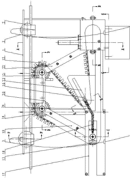
[0029] The cable robot drives the carrier, and its composition includes: frame 1, walking auxiliary wheel 2 is installed on the frame, the installation rope 3 is connected to the frame, and the dismounting combination rod 4 is connected to the frame through a hinge Above, the torsion spring 5 is connected between the disassembly combination lever and the frame, the disassembly combination lever is connected with the disassembly rope 6, the drive motor 7 is connected under the frame, and the power of the drive motor The output shaft is connected with the worm 8, and the worm is connected with the worm wheel 9, and the worm wheel is installed on the drive shaft 10, and the drive shaft is connected with the rod chain combination. During use, the installation rope 3 is straddled by the model airplane, and then the installation rope 3 is pulled on the ground to complete the installation of the drive carrier. The drive motor 7 drives the worm 8 to rotate, so that the worm wheel 9 r...

Embodiment 2

[0031] The cable robot drives the carrier, the rod-chain combination includes a driving sprocket 11 installed on the drive shaft, and the driving sprocket is connected to the sliding sprocket 13 and the rear driven sprocket sequentially through a chain 12 14. The front driven sprocket 15 and the compression sprocket 16, the sliding sprocket is installed on the horizontal slideway 17 under the frame and connected with the frame through a rear tension spring 18, A strut 19 is connected between the sliding sprocket and the rear driven sprocket, a connecting rod 20 is connected between the rear driven sprocket and the front driven sprocket, and the connecting rod is connected to the stopper. Plate 21, a swing bar 22 is connected between the front driven sprocket and the frame, and the compression sprocket is installed on the inclined slideway 23 below the frame and is connected with the frame. Connect by front extension spring 24 between the frames. The sliding sprocket is pull...

Embodiment 3

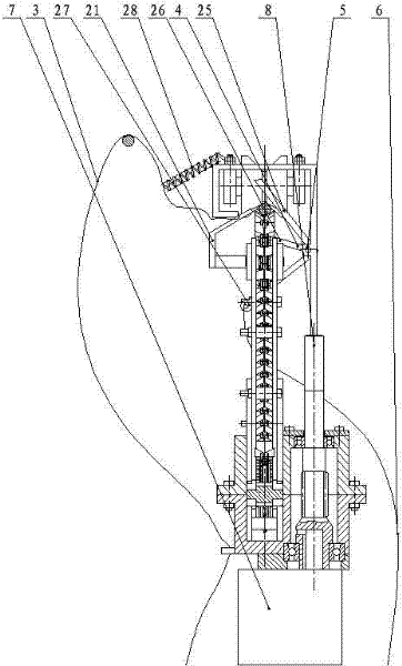
[0033] The cable robot drives the carrier, and the disassembly assembly rod has a cable lever fork 25, a rod chain lever fork 26, and a disassembly pull rod fork 27 connected by the disassembly rope. When dismounting the drive carrier, pull the dismounting rope to make the dismounting pull bar 27 drive the dismounting combination lever to rotate. Out of the cable at the predetermined position, slowly put down the drive carrier to complete the disassembly, and the disassembly combination lever 4 is reset by the reset torsion spring 5.


PUM


Abstract

The invention relates to a cable robot driving carrier. A present cable robot driving carrier needs to be installed at a high altitude by workers, if meeting meteorological disasters of ice rain and the like, high altitude installation is more dangerous, and a plurality of driving carriers can not be used universally and are not suitable for single field operation. The cable robot driving carrier comprises a rack (1) which is installed with a walking auxiliary wheel (2) and is connected with an installation rope (3). A dismounting compound rod (4) is connected to the rack through a hinge. A torsion spring (5) is connected between the dismounting compound rod and the rack. The dismounting compound rod connects with a dismounting rope (6). A lower part of the rack connects with a driving motor (7). A power output shaft of the driving motor connects with a worm (8). The worm connects with a worm gear (9). The worm gear is installed on a driving shaft (10) which is connected with a rod chain combination. The cable robot driving carrier is used for a cable driving carrier.

Description

technical field [0001] The invention relates to a cable robot drive carrier. Background technique [0002] For the driving mechanism of the cable, although there are many types, such as: Sawada et al. of Tokyo Electric Power Company have developed a mobile robot for inspection of optical fiber composite overhead ground wires, which has an arc-shaped arm to overcome obstacles; TRC Corporation of the United States has developed a cantilever autonomous robot. The prototype of the line patrol robot uses the cantilever mechanism to overcome obstacles, etc. All cable-driven carriers need to be manually installed at high altitudes. In case of meteorological disasters such as freezing rain, high-altitude installation will be more dangerous. The quality is increased, the control is complicated, and the cost is increased. In order to adapt to various wire diameters, a complex driving mechanism is provided, so that many driving carriers cannot be popularized and used, and are not su...

Claims


Application Information

Patent Timeline
IPC IPC(8): H02G1/02F16H7/06
Inventor 郝广平李洪喆王志宏仲昭楠孟凡竹
Owner HARBIN UNIV OF SCI & TECH
Why Eureka
Try Eureka