Touch type key and detection method therefor

A touch and key technology, applied in the direction of keyboard coding, electrical components, electronic switches, etc., can solve the problems of complex key structure and high cost, and achieve the effect of strong anti-interference ability, good ease of use, and simple peripheral circuits.

Active Publication Date: 2012-03-28
FEITIAN TECHNOLOGIES
View PDF5 Cites 4 Cited by
  • Summary
  • Abstract
  • Description
  • Claims
  • Application Information

AI Technical Summary

Problems solved by technology

[0004] The touch button can detect whether the button is pressed through some components with different functions combined with the progra

Method used


Image

  • Touch type key and detection method therefor
  • Touch type key and detection method therefor
  • Touch type key and detection method therefor

Examples


Embodiment 1

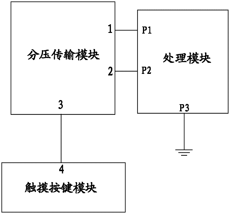
[0087] see figure 1 , is a schematic diagram of a block structure of a touch button provided in Embodiment 1 of the present invention;

[0088] This embodiment provides a touch button, such as figure 1 As shown, including touch button module, voltage division transmission module and processing module;

[0089] Touch button module; used to receive the touch signal of the human body, and transmit the touch signal to the voltage divider transmission module through the terminal 3 of the voltage divider transmission module; when the human body touches the touch button module, the touch button module is equivalent to generating a certain the impedance;

[0090] Voltage division transmission module: used to receive the signal output by the terminal P1 of the processing module through the terminal 2 of the voltage division transmission module, and receive the touch signal transmitted by the touch button module through the terminal 3 of the voltage division transmission module. The ...

Embodiment 2

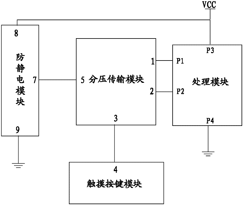
[0115] see Figure 4 , which is a schematic diagram of the circuit structure of the first touch button provided in Embodiment 2;

[0116] The processing module is MCU, the voltage division transmission module includes capacitors C1, C2 and resistor R, and the touch key includes Touch Key; wherein, the endpoints P1 and P2 of the MCU are connected to the capacitors C1 and C2 respectively, and the grounding endpoint of the MCU is grounded; the endpoints P1 and The terminals P2 are two I / O ports in the MCU respectively; the other terminals of the capacitors C1 and C2 are both connected to one terminal of the resistor R, and the other terminal of the resistor R is connected to the touch button.

[0117] see Figure 5 , for Example 2 Figure 4 The schematic diagram of the waveform before and after the touch of the first key; Figure 5 is in Figure 4 It is detected on the touch button shown, the input waveform is the waveform measured at the P1 port of the MCU; the output wavefo...

Embodiment 3

[0126] see Figure 8 , provided for this example based on Figure 4 The flow chart of the detection method of the first kind of touch button shown; specifically includes as follows:

[0127] S11: power on, initialize the input port and output port;

[0128] S12: Output high level to the output port and delay for a period of time, then output low level to the output port;

[0129] Preferably, in this embodiment, the high level is recorded as 1, and the low level is recorded as 0. S12 can also be: write 1 to the output port and delay for a period of time, and then write 0 to the output port;

[0130] Preferably, the delay time can be 5ms;

[0131] S13: receiving an input signal from an input port;

[0132] S14: Record the delay time T0 required for the state of the current input port to change from low level to high level;

[0133] When the state of the output port is low level, the processing module starts timing, and starts to detect the state of the input port, until the...


PUM


Abstract

The invention provides a touch type key and a detection method therefor. The touch type key comprises a touch key module, a partial pressure transmission module, and a processing module, wherein the partial pressure transmission module comprises three end nodes including an end node 1, an end node 2 and an end node 3; the processing module comprises three end nodes including an end node P1, an end node P2, and a grounding end node; the end node P1 and the end node P2 of the processing module are connected with the end node 1 and the end node 2 of the partial pressure transmission module respectively, and the grounding end node of the processing module is grounded; and the touch key module has one end node 4 connected with the end node 3 of the partial pressure transmission module. The touch type key provided by the invention is realized through a most basic component, and has the advantages of low cost, strong anti-interference ability, simple peripheral circuit, good use easiness, simplicity in operation, and long service cycle.

Description

technical field [0001] The invention relates to a touch key and a detection method thereof, belonging to the field of electronic products. Background technique [0002] At present, the mechanical keys used in many devices occupy a large volume, have a short life, are difficult to operate, and are expensive. [0003] With the development of control technology, touch buttons have gradually replaced mechanical buttons. Products using touch buttons usually have more convenient operation, more fashionable and beautiful appearance, reliability and durability, no spark interference, no mechanical movement, simple structure, and can be fully enclosed. installation and many other advantages. [0004] The touch button can detect whether the button is pressed through some components with different functions combined with the programming of the MCU; however, the existing touch button structure is relatively complicated, and the cost of implementation is relatively high. Contents of t...

Claims


Application Information

Patent Timeline
IPC IPC(8): H03K17/96H03M11/02
Inventor 陆舟于华章
Owner FEITIAN TECHNOLOGIES
Why Eureka
Try Eureka