Antenna and wireless communication apparatus

A technology of wireless communication devices and antennas, applied in the direction of antenna supports/mounting devices, antennas, resonant antennas, etc., can solve the problem that the inductance component is not provided, reduce spurious radiation, and suppress the generation of high-order harmonics Effect

Inactive Publication Date: 2012-03-28
MURATA MFG CO LTD
View PDF3 Cites 2 Cited by
  • Summary
  • Abstract
  • Description
  • Claims
  • Application Information

AI Technical Summary

Problems solved by technology

In addition, when the PIN diode 14 is in the ON state, more current flows through the PIN diode 14 than the inductor 13, and almost no curren

Method used


Image

  • Antenna and wireless communication apparatus
  • Antenna and wireless communication apparatus
  • Antenna and wireless communication apparatus

Examples


Embodiment Construction

[0032] The structure of the antenna according to the embodiment of the present invention and a wireless communication device including the antenna will be described with reference to the respective drawings.

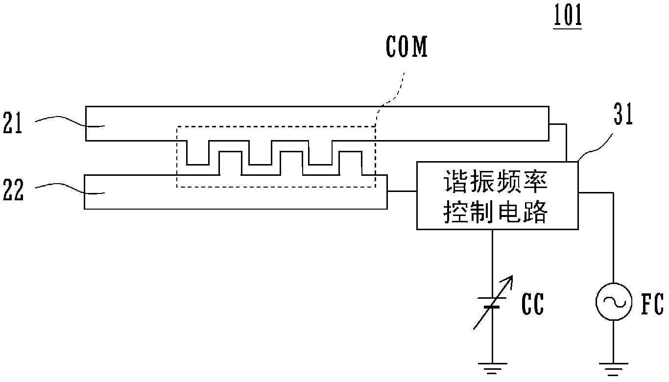
[0033] figure 2 It is an equivalent circuit diagram showing the structure of the antenna according to the embodiment of the present invention and the antenna embedded in the casing of a wireless communication device such as a mobile phone terminal including the antenna.

[0034] exist figure 2 Among them, the first radiation electrode 21 and the second radiation electrode 22 constitute an antenna element. The first radiation electrode 21 and the second radiation electrode 22 are provided with a comb portion COM that generates capacitance by facing each other. The tip of the first radiation electrode 21 and the second radiation electrode 22 is open, and the resonance frequency control circuit 31 is connected to the base. A power supply circuit (power supply unit) FC ...


PUM


Abstract

Disclosed are an antenna provided with a resonant frequency control circuit and having a design which suppresses emission (reradiation) of harmonic signals generated when the antenna receives radio waves from the outside, and a wireless communication apparatus provided with the same. A first radiating electrode (21) and a second radiating electrode (22) are provided with comb sections (COM) which generate capacitance by facing each other. If emissions of transmission radio waves from a different antenna near the antenna (101) are received, a portion will be emitted to the antenna (101), and harmonic signals will be generated by a variable capacitance element inside the resonant frequency control circuit (31). However, an LC resonant circuit (tank circuit) is formed by the inductance component of the first radiating electrode (21) and second radiating electrode (22) and the capacitance component generated at the comb sections (COM), so even if emissions from the different antenna are received, the radio waves of the basic mode are confined by the resonant frequency of the LC resonant circuit, and harmonic reradiation (spurious emission) power is reduced.

Description

technical field [0001] The present invention relates to an antenna used in wireless communication devices such as mobile phone terminals and a wireless communication device including the same. Background technique [0002] Patent Document 1 discloses a multi-band compatible antenna in which a resonance frequency is changed by controlling a voltage using a single antenna element. Here, the antenna of Patent Document 1 will be described. [0003] figure 1 It is a perspective view of the antenna disclosed in Patent Document 1. FIG. The antenna 1 includes a dielectric base 3 mounted on a circuit board 2 of a wireless communication device, a feeding radiation electrode 4 provided on the base 3 , and a frequency switching circuit 5 electrically connected to the feeding radiation electrode 4 . [0004] The feeding radiation electrode 4 is a λ / 4 type radiation electrode, and is formed across a plurality of surfaces of the upper surface 3 u, the front end surface 3 f, and the side...

Claims


Application Information

Patent Timeline
IPC IPC(8): H01Q1/52H01Q1/24H01Q21/30
CPCY02B60/50H01Q1/243H01Q9/42
Inventor 堀田笃
Owner MURATA MFG CO LTD
Why Eureka
Try Eureka