Locking sheet groove type blade assembled radial line deviation measuring apparatus of steam turbine rotor
A technology for assembling steam turbine rotors and blades, which is applied to mechanical measuring devices, measuring devices, and mechanical devices, etc., can solve the problem of inability to measure the radiation deviation of the secondary and final blades of large-scale low-pressure rotors, cannot guarantee the measurement accuracy, and is inconvenient to measure, etc. It can solve the problem of radiation deviation measurement, reduce the weight and improve the measurement accuracy.
- Summary
- Abstract
- Description
- Claims
- Application Information
AI Technical Summary
Problems solved by technology
Method used
Image
Examples
specific Embodiment approach 1
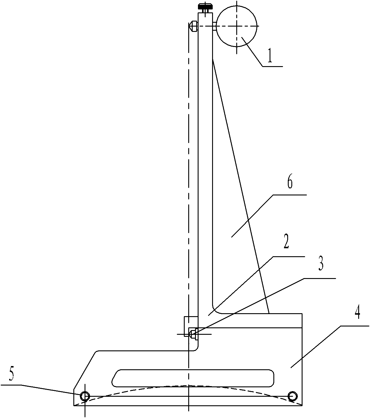
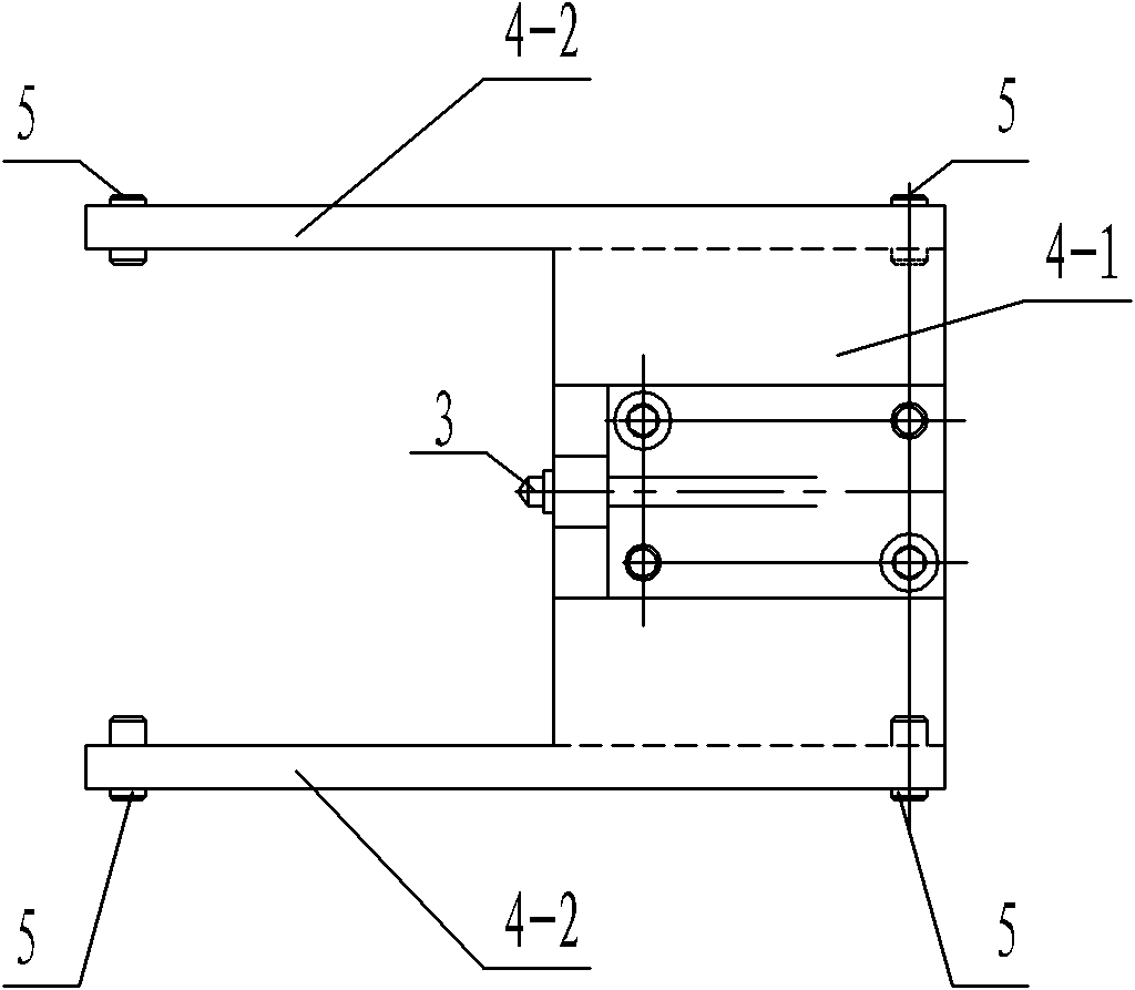
[0010] Specific implementation mode one: combine figure 1 and figure 2 To illustrate this embodiment, the steam turbine rotor lock groove blade assembly radiation deviation measurement tool of this embodiment includes a dial indicator 1, an L-shaped bracket 2, a positioning pin 3, a base 4, and four cylindrical pins 5; the base 4 includes a main board 4-1 and two side plates 4-2, a side plate 4-2 is respectively arranged on the front and rear sides of the main board 4-1, and two cylindrical pins 5 are installed on the bottom surface of each side plate 4-2, L-shaped Bracket 2 is installed on the upper end face of main board 4-1, and alignment pin 3 is installed on the left side of main board 4-1, and dial indicator 1 is installed on the vertical plate of L-shaped support 2, and the meter top of dial indicator 1 Point and the apex of positioning pin 3 are on the same vertical line.
specific Embodiment approach 2
[0011] Specific implementation mode two: combination figure 1 and figure 2 Describe this embodiment, the steam turbine rotor lock groove blade assembly radiation deviation measurement tool of this embodiment includes a rib plate 6, the upper end of the rib plate 6 is connected with the vertical plate of the L-shaped bracket 2, and the lower end of the rib plate 6 is connected with the L-shaped bracket 2. Base plate connection for bracket 2. With such arrangement, the structure is more stable. Other compositions and connections are the same as in the first embodiment.
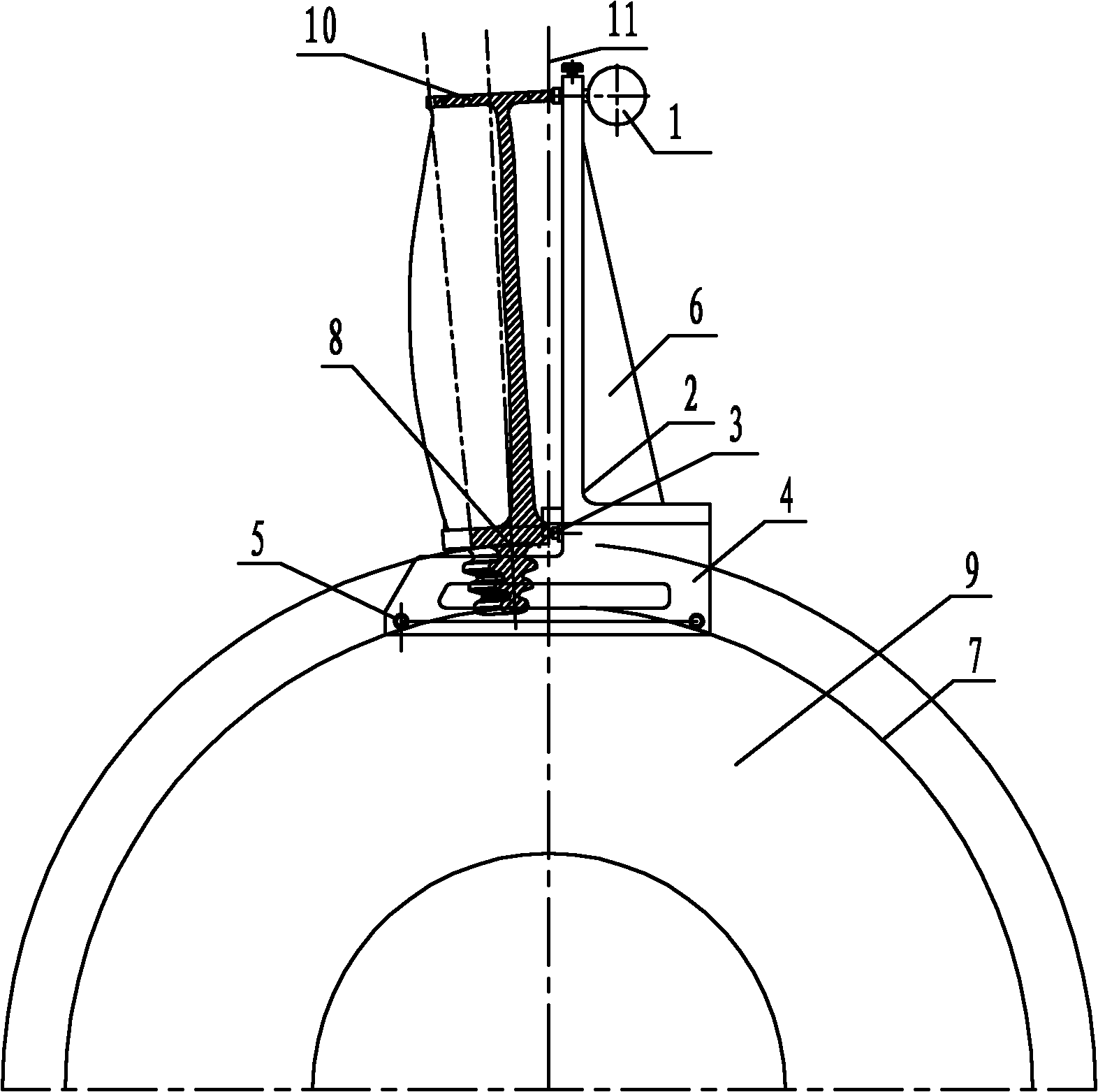
[0012] How it works: combined image 3 and Figure 4 To explain the working principle, first adjust the dial gauge 1 to zero, and the connection line between the top of the dial gauge 1 and the top of the positioning pin 3 is on the perpendicular bisector of the line connecting the two cylindrical pins 5; then, install the base 4 On the rotor impeller 9, the cylindrical pin 5 on the side plate 4-2 falls on...
PUM
 Abstract
Description
Claims
Application Information
 - R&D
- Intellectual Property
- Life Sciences
- Materials
- Tech Scout
- Unparalleled Data Quality
- Higher Quality Content
- 60% Fewer Hallucinations
Browse by: Latest US Patents, China's latest patents, Technical Efficacy Thesaurus, Application Domain, Technology Topic, Popular Technical Reports.
© 2025 PatSnap. All rights reserved.Legal|Privacy policy|Modern Slavery Act Transparency Statement|Sitemap|About US| Contact US: help@patsnap.com


