Lateral restraining device for load test of steel-structure compression member

A technology for loading test and compression components, which is applied in the field of steel structures in structural engineering, can solve problems such as the inability to arrange large-scale reaction frames, difficulty in installing reaction frames, and limited number of supports, and achieves easy processing, simple structure, and reduced The effect of friction

Active Publication Date: 2012-04-04
TSINGHUA UNIV
View PDF5 Cites 23 Cited by
  • Summary
  • Abstract
  • Description
  • Claims
  • Application Information

AI Technical Summary

Problems solved by technology

However, the long-column compression testing machine does not provide a lateral support device, and it is often necessary to arrange a large-scale support and reaction frame around it during the test, but the installation of the reaction frame is difficult, the number of supports is limited, and a large site is required. The laboratory cannot even arrange a large reaction force frame

Method used


Image

  • Lateral restraining device for load test of steel-structure compression member
  • Lateral restraining device for load test of steel-structure compression member
  • Lateral restraining device for load test of steel-structure compression member

Examples


Embodiment Construction

[0019] The present invention will be further described below in conjunction with the embodiments and the accompanying drawings.

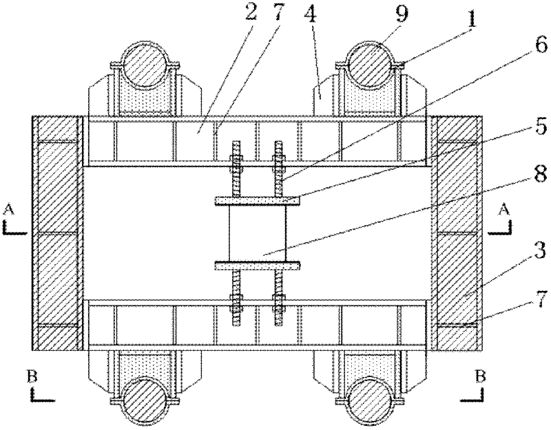
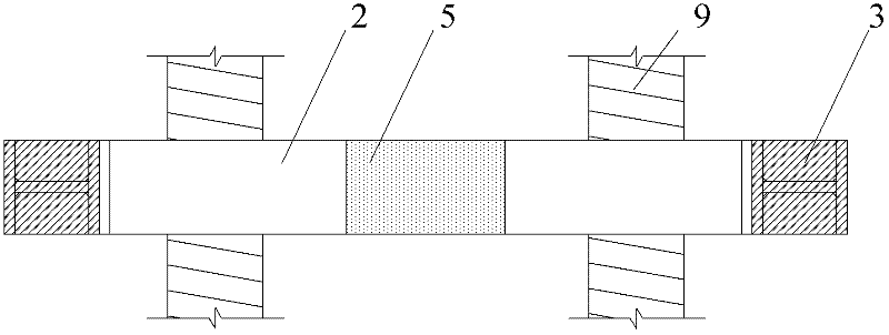
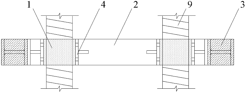
[0020] figure 1 It is a structural top view schematic diagram of an embodiment of a lateral restraint device for a loading test of a steel structure compression member, figure 2 and image 3 respectively figure 1 Structural sectional view along A-A direction and structural sectional view along B-B direction. The lateral restraint device of the steel structure compression member loading test is a detachable structure, which consists of a screw clamp 1, a supporting beam 2, a self-balancing beam 3, a screw clamp base 4, a specimen splint 5 and a splint screw 6. Both the support beam 2 and the self-balancing beam 3 are H-shaped steel structures. There are 4 holes in the middle part of the inner flange of the supporting beam 2. The inner flanges of the front and rear two supporting beams 2 are opposite and parallel to each other, and the inner fla...


PUM


Abstract

The invention belongs to the technical field of the steel structure of a structural engineering, in particular to a lateral restraining device for a load test of a steel-structure compression member. The inner-side flange of a front support transverse beam and the inner-side flange of a back support transverse beam are opposite to each other and are in parallel with each other, the inner-side flange of a left self-balancing transverse beam and the inner-side flange of a right self-balancing transverse beam are opposite to each other and are respectively in bolt connection with left ends and right ends of the two support transverse beams, so that a rectangular self-balancing counter-force frame is formed, two test piece clamping plates are opposite to each other face to face between the support transverse beams, are in parallel with each other, and are respectively fixed in the middle of the inner-side flanges of the two support transverse beams by four clamp plate screw rods and matched screw nuts, a distance between the two test pieces clamp plates is adjusted by adjusting the matched screw nuts, a plurality of lead screw clamp bases are fixedly arranged on the outer-side flangesof the support transverse beams, a plurality of lead screw clamps are fixedly connected with the lead screw clamp bases, the lead screw clamps are clamped on a plurality of lead screws of a long-column pressure tester, the self-balancing counter-force frame is horizontally arranged among the lead screws, and the side faces of a test piece are clamped by the two test pieces clamp plates. The effective lateral support outside an unstable plane of the test piece to be pressured is realized, so that the device is suitable for the research of a performance test for the whole stability of the compression member.

Description

technical field [0001] The invention belongs to the technical field of structural engineering steel structures, and in particular relates to a lateral restraint device for loading tests of compression members of steel structures. Background technique [0002] The overall stability of steel structure compression members is one of the most important research topics in the field of steel structure, and long-column compression testing machines are usually used for experimental research. In the absence of lateral bracing, steel columns in compression usually lose stability about the weak axis of the section. In order to study the overall stability of the steel column around the strong axis, the necessary lateral support conditions must be provided, and the calculated length of the steel column around the weak axis can be reduced to ensure that the instability around the strong axis occurs. However, the long-column compression testing machine does not provide a lateral support de...

Claims


Application Information

Patent Timeline
Patent Type & Authority Applications(China)
IPC IPC(8): G01N3/02
Inventor 施刚班慧勇石永久王元清
Owner TSINGHUA UNIV
Why Eureka
Try Eureka