Fluid storage and purification integrated device for fuel cell and fluid cooling system of fuel cell

A technology for fuel cells and cooling systems, applied in the direction of fuel cell additives, etc., can solve the problems of electrode overheating, increase operating costs, affect performance and life, reduce fluid control components and operations, improve reliability, and reduce sealing points. Effect

Inactive Publication Date: 2012-04-04
武汉银泰科技燃料电池有限公司
View PDF4 Cites 7 Cited by
  • Summary
  • Abstract
  • Description
  • Claims
  • Application Information

AI Technical Summary

Problems solved by technology

At the same time, the cooling liquid does not flow into the liquid storage tank during the circulation process, that is, the cooling liquid in the liquid storage tank does not participate in the flow process of the cooling liquid, which cannot guarantee the liquid storage when the ambient temperature is lower than 0°C. The liquid in the tank can still maintain a liquid state, so additional heating and heat preservation must be carried out on the liquid storage tank, which also increases the operating cost, and at the same time increases the corresponding control system
Thirdly, the coolant will generate air bubbles at the operating temperature of the fuel cell, and the air bubbles will affect the uniform distribution of the coolant among the single electrodes in the stack; if there are more air bubbles in the coolant entering a certain single electrode, The coolant that actually enters the single electrode will be less, and the heat taken away by the coolant will be less, so the single electrode will be hotter than other electrodes. In severe cases, the electrode will overheat, affecting its performance and life.

Method used


Image

  • Fluid storage and purification integrated device for fuel cell and fluid cooling system of fuel cell
  • Fluid storage and purification integrated device for fuel cell and fluid cooling system of fuel cell
  • Fluid storage and purification integrated device for fuel cell and fluid cooling system of fuel cell

Examples


Embodiment Construction

[0027] The present invention will be further described below in conjunction with the drawings to help understand the content of the present invention.

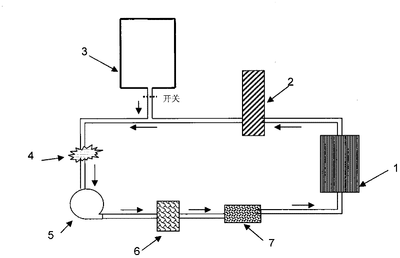
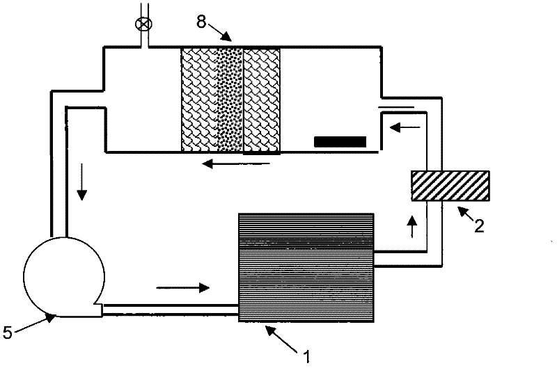
[0028] Such as figure 2 Shown here is a fuel cell liquid cooling system of the present invention, which includes a pump 5 and a radiator 2 installed on the fuel cell coolant circulation pipeline, and also includes a liquid storage tank installed between the pump 5 and the radiator 2 through a pipeline. Purification integrated device 8. When the cooling liquid passes through the stack 1, the heat generated by the reaction is taken out, and when it passes through the radiator 2, the cooling liquid releases heat through the radiator. The cooled cooling liquid enters the integrated liquid storage purification device 8, and the integrated liquid storage purification device 8 After filtration and / or deionization purification treatment, the battery is forced to be fed into the stack through a pump to force the circulation of the coolin...


PUM


Abstract

The invention discloses a fluid storage and purification integrated device for a fuel cell and a fluid cooling system of the fuel cell. The fluid storage and purification integrated device comprises a box body, a fluid storage chamber is arranged in the box body and is used for storing cooling fluid, the top part of the box body is provided with a gas release valve, the box body is provided with a cooling fluid inlet and a cooling fluid outlet, the cooling fluid inlet and the cooling fluid outlet are communicated with the fluid storage chamber, the cooling fluid outlet is arranged in the middle lower part of the box body, a porous cooling fluid purification element is also arranged in the fluid storage chamber and between the inlet and the outlet, and the effective volume of the fluid storage chamber non-filled by the purification element can meet fluid storage requirements for supplying the cooling fluid to the cooling circulation system of the fuel cell. Since the fluid storage, purification and even heating are integrated in the integrated device, the pipeline of the cooling circulation system of the fuel cell can be simplified and reduced, the number of sealing points can be reduced, the influence of bubbles on distribution of the cooling fluid in galvanic pile can be reduced, the number of fluid supply control components and operation can also be reduced, all the cooling fluid can be maintained in the fluid state in low-temperature environments, and the operating reliability of the system can be improved.

Description

Technical field [0001] The invention belongs to the field of energy, in particular to the field of new fuel cell energy, relates to a liquid cooling system of a fuel cell, and provides a cooling liquid storage device that integrates liquid storage, filtration, deionization, and heating and heat preservation, and Its connection and use in the fuel cell system is suitable for all types of fuel cells that require liquid cooling, especially proton exchange membrane fuel cells. It is a key project of the "863 Program" of the Ministry of Science and Technology of China, "5kW fuel cell key materials and system integration technology development" (project number: 2009AA034400). Background technique [0002] In order to solve the urgent problems of environmental pollution, the greenhouse effect and the increasingly depleted fossil fuels, countries all over the world are paying great attention to fuel cell technology and industrialization, because the fuel cell is a high-efficiency and cle...

Claims


Application Information

Patent Timeline
Patent Type & Authority Applications(China)
IPC IPC(8): H01M8/04
CPCY02E60/50
Inventor 齐志刚胡浩博
Owner 武汉银泰科技燃料电池有限公司
Why Eureka
Try Eureka