Positioning force compensating type linear permanent magnet synchronous motor

A permanent magnet synchronous motor and positioning force technology, applied in the direction of electrical components, electromechanical devices, electric components, etc., can solve the problems of reducing the effective thrust of the motor and increasing the processing cost of the motor, and achieve high motor efficiency, small positioning force, and reduced difference small effect

Active Publication Date: 2013-05-08
HARBIN INST OF TECH
View PDF5 Cites 0 Cited by
  • Summary
  • Abstract
  • Description
  • Claims
  • Application Information

AI Technical Summary

Problems solved by technology

Even if the above methods are used at the same time, it is impossible to completely eliminate the thrust fluctuation caused by the motor structure, and it may also increase the processing cost of the motor and reduce the effective thrust of the motor

Method used


Image

  • Positioning force compensating type linear permanent magnet synchronous motor
  • Positioning force compensating type linear permanent magnet synchronous motor
  • Positioning force compensating type linear permanent magnet synchronous motor

Examples


specific Embodiment approach 1

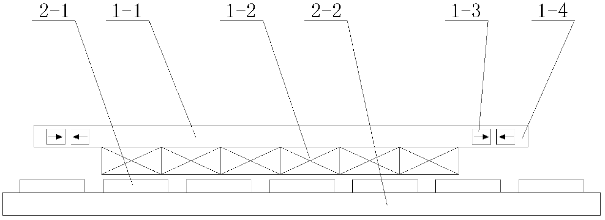
[0042] Specific implementation mode one: the following combination figure 1 Describe this embodiment, the positioning force compensation type linear permanent magnet synchronous motor described in this embodiment includes a primary and a secondary, an air gap between the primary and the secondary, and the primary includes an armature core 1-1 and an armature Winding 1-2, the armature winding 1-2 is a surface mount structure,

[0043] The primary also includes a magnetic isolation permanent magnet 1-3, and the armature iron core 1-1 is embedded with a magnetic isolation permanent magnet 1-3 in the armature iron core 1-1 at both ends of the relative movement direction between the armature core 1-1 and the secondary. The permanent magnet 1-3 runs through the armature core 1-1 in parallel.

[0044] The secondary in this embodiment is composed of a secondary permanent magnet 2-1 and a secondary yoke 2-2. The armature winding 1-2 is pasted and fixed on the air gap side surface of...

specific Embodiment approach 2

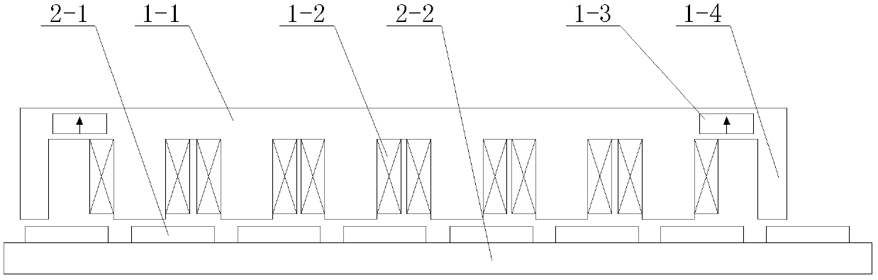
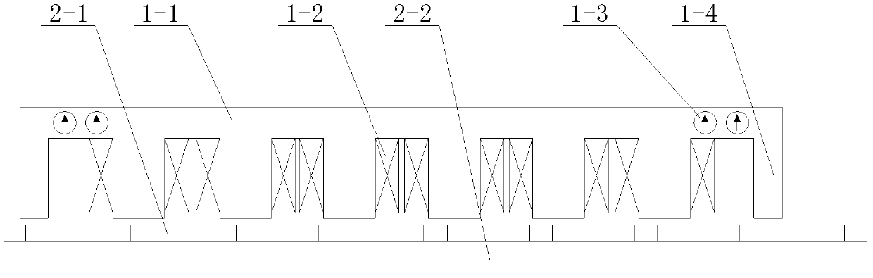
[0046] Specific implementation mode two: the following combination Figure 2 to Figure 7Describe this embodiment, the positioning force compensation type linear permanent magnet synchronous motor described in this embodiment includes a primary and a secondary, an air gap between the primary and the secondary, and the primary includes an armature core 1-1 and an armature winding 1-2, the primary is a cogged structure,

[0047] The primary also includes a magnetic isolation permanent magnet 1-3 and a compensation tooth 1-4, and the two ends of the armature core 1-1 along the relative movement direction of the secondary are respectively provided with a compensation tooth 1-4. The yokes at both ends of the 1-1 are embedded with magnetic isolation permanent magnets 1-3, and the magnetic isolation permanent magnets 1-3 run through the yoke of the armature core 1-1 in parallel.

[0048] The secondary in this embodiment is composed of a secondary permanent magnet 2-1 and a secondary ...

specific Embodiment approach 3

[0050] Specific implementation mode three: the following combination Figure 2 to Figure 4 Describe this embodiment, this embodiment is a further description of Embodiment 1 or 2, the magnetic isolation permanent magnet 1-3 at each end of the armature core 1-1 is one or two, and the magnetic isolation permanent magnet 1-3 The magnetization direction of 3 is perpendicular to the moving direction, and the magnetization directions of all magnetic separation permanent magnets 1-3 are the same.


PUM


Abstract

The invention relates to a positioning force compensating type linear permanent magnet synchronous motor which belongs to the technical field of motors and solves the problems that the existing method for reducing the fluctuation of the push force of the linear motor only can restrain the fluctuation of the motor to a certain extent and simultaneously reduces the effective push force of the motor. An air gap is arranged between a primary and a secondary of the motor, the primary comprises an armature iron core and an armature winding and is in a structure of surface mounted armature winding or a cogging structure, the positioning force generated by the interaction of compensating parts and a secondary permanent magnet and the positioning force generated by interaction of the primary iron core and the secondary permanent magnet can be mutually counteracted through the addition of the compensating parts at the yoke parts of two ends of the armature iron core of the primary and using permanent magnets to perform magnetism isolation, so that the acting forces at the front end part and the rear end part of the motor are mutually counteracted. The detent force compensating type linear permanent magnet synchronous motor is suitable for linear permanent magnet synchronous motors.

Description

technical field [0001] The invention relates to a positioning force compensation type linear permanent magnet synchronous motor, which belongs to the technical field of motors. Background technique [0002] Thrust fluctuations are the cause of vibration and noise of linear motors, especially when the motor is running at low speed, thrust fluctuations may cause resonance, thereby deteriorating the servo operation characteristics of the motor, such as positioning accuracy. [0003] There are many reasons for the thrust fluctuation of the linear motor, including the thrust fluctuation caused by the end effect and the cogging effect, the influence of the manufacturing accuracy of the linear motor on the thrust output of the linear motor, and the mismatch between the phase current rectification waveform and the coil. The thrust output of the linear motor changes. [0004] For permanent magnet linear motors, due to the existence of the longitudinal end of the primary iron core an...

Claims


Application Information

Patent Timeline
Patent Type & Authority Patents(China)
IPC IPC(8): H02K41/03
Inventor 寇宝泉张赫张鲁郭守仑
Owner HARBIN INST OF TECH
Why Eureka
Try Eureka