Set-top box and standby control method thereof

A set-top box and standby state technology, applied in image communication, selective content distribution, electrical components, etc., can solve the problems of power criticality and exceeding the specification requirements, and achieve the effect of reducing power consumption, low cost, and reducing standby power consumption

Active Publication Date: 2012-04-04
BEIJING CYCLE CENTURY DIGITAL TECH
View PDF5 Cites 11 Cited by
  • Summary
  • Abstract
  • Description
  • Claims
  • Application Information

AI Technical Summary

Problems solved by technology

[0009] This circuit relies solely on switches (usually MOS tubes) to control the standby power consumption. Under the required standby specification of less than 1W, when the efficiency of some power chips is not high, the power in the standby state sometimes appears power critical or Situations exceeding specification requirements

Method used


Image

  • Set-top box and standby control method thereof
  • Set-top box and standby control method thereof
  • Set-top box and standby control method thereof

Examples


Embodiment 1

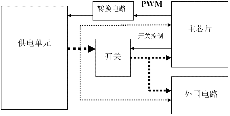
[0043] Embodiment 1. A set-top box, such as image 3 shown, including:

[0044] switch, main chip including multiple units;

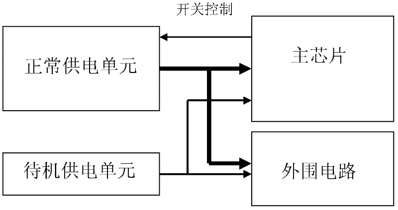
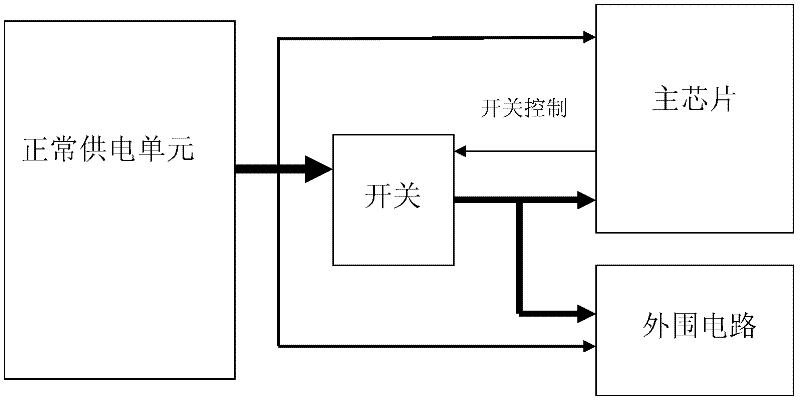
[0045] a power supply unit, configured to directly output voltage to units related to the standby state in the main chip, and output voltage to units in the main chip not related to the standby state through the switch;

[0046] The main chip is used to turn off the switch when ready for standby, and adjust the width of the output pulse; turn on the switch when waking up the system, and restore the width of the output pulse;

[0047] The conversion circuit is used for changing the voltage output by the power supply unit according to the width of the output pulse of the main chip.

[0048] In this embodiment, the set-top box may also include a peripheral circuit, and the power supply unit is also used to directly output voltage to the units related to the standby state in the peripheral circuit, and supply voltage to the peripheral circuit and the stan...

Embodiment 2

[0071] Embodiment 2, a standby control method of a set-top box, the set-top box includes at least a main chip, and the method includes:

[0072] When ready to stand by, stop outputting voltage to units in the main chip that have nothing to do with the standby state; adjust the width of the output pulse of the main chip;

[0073] When waking up the system, restore the width of the output pulse of the main chip, and restore the output voltage to the units in the main chip that have nothing to do with the standby state;

[0074] According to the adjusted width of the output pulse, the level of the voltage output to the units related to the standby state in the main chip is changed.

[0075] In this embodiment, the adjustment of the width of the output pulse of the main chip refers to widening the width of the output pulse of the main chip.

[0076] In this embodiment, the adjusted pulse width can reduce the output voltage of the power supply unit and is sufficient for use in the...


PUM


Abstract

The invention discloses a set-top box and a standby control method thereof. The set-top box comprises a switch, a power supply unit and a converting circuit, wherein the switch comprises a master chip with a plurality of units; the power supply unit is used for directly outputting voltage to the units, which are related to the standby state, in the master chip and used for outputting voltage to the units, which are not related to the standby state, in the master chip through the switch; the converting circuit is used for changing the voltage output by the power supply unit according to the width of an output impulse of the master chip; the master chip is used for switching off the switch when the set-top box is to be standby and for adjusting the width of the output impulse; and when the system is aroused, the switch is switched on, and the width of the output impulse is restored. The invention can further reduce the power consumption of a main board in the standby state under the premise that the functions of normal working and standby arousing of the set-top box are met.

Description

technical field [0001] The invention relates to the field of cable television, in particular to a set-top box and a standby control method thereof. Background technique [0002] In traditional applications, the single-chip standby circuit is used to control the standby and wake-up functions of the set-top box, but the single-chip standby can only respond to the traditional infrared remote control application, and cannot meet the application of smart terminal users using 2.4G wireless remote control. In a circuit that uses the main chip to stand by, because the power consumption of the high-load power supply in the standby state is difficult to control, the stand-by control of the main chip GPIO (General Purpose Input Output, general-purpose input / output port) has a high standby power consumption of the main board. The problem. [0003] The existing main chip standby processing scheme mainly includes: [0004] One method is to design a separate power supply for the main chi...

Claims


Application Information

Patent Timeline
IPC IPC(8): H04N21/43
Inventor 许生明郭先概陈烨高伟李登彪
Owner BEIJING CYCLE CENTURY DIGITAL TECH
Why Eureka
Try Eureka