Supercharge Your Innovation With Domain-Expert AI Agents!

Double-throat-type gas supersonic velocity cyclone separating device

A cyclone separation device and supersonic technology, which are applied in separation methods, dispersed particle separation, and production of fluids, etc., can solve problems such as unfavorable droplet growth, weak cyclone ability, damage to low temperature and low pressure environments, and avoid boundary layer separation effects. , The effect of reducing frictional resistance loss and supersonic flow stability

Inactive Publication Date: 2013-09-11
文闯
View PDF19 Cites 0 Cited by
  • Summary
  • Abstract
  • Description
  • Claims
  • Application Information

AI Technical Summary

Problems solved by technology

[0004] The main structure of the supersonic cyclone separator includes components such as Laval nozzle, cyclone device and diffuser pipe. According to the installation position of the cyclone device, there are two typical structures of the supersonic cyclone separator: one The swirl device is installed in the supersonic section behind the nozzle to generate the swirl, so the swirl device is also called the supersonic wing. In this kind of structure, since the speed conversion occurs under the supersonic condition, the supersonic wing is easy to generate shock. Waves destroy the low-temperature and low-pressure environment, which is not conducive to the growth of droplets and reduces the separation efficiency of the supersonic separator. Representative patents mainly include foreign US 6513345 B1, US 6524368B2, US 3773825 B2, US 6962199 B1, US 7261766 B2.US 7318849 B2, US 7494535 B2, WO2003 / 092850 A1, WO 2004 / 020074 A1 and domestic ZL 200410074338.8, etc.; the other is to install the swirl device at the inlet of the nozzle so that the gas enters the nozzle in the form of swirl The expansion and cooling, the main patents are foreign US7357825 B2, US 2008 / 0196581 A1, US 2010 / 0147021 A1, EP 1131588 B1, US 6372019 B1, US 2010 / 0147023 A1, domestic number, zl 200910023458.8 200910081813.7, 200910093744.1, 201010597341.3, etc. The disadvantage is that the swirling capacity of the swirl device is weaker than that of the supersonic wing, which reduces the separation effect of the supersonic separator

Method used


Image

  • Double-throat-type gas supersonic velocity cyclone separating device
  • Double-throat-type gas supersonic velocity cyclone separating device
  • Double-throat-type gas supersonic velocity cyclone separating device

Examples


Embodiment Construction

[0016] The structural features and working principles of the present invention will be further described below in conjunction with the accompanying drawings.

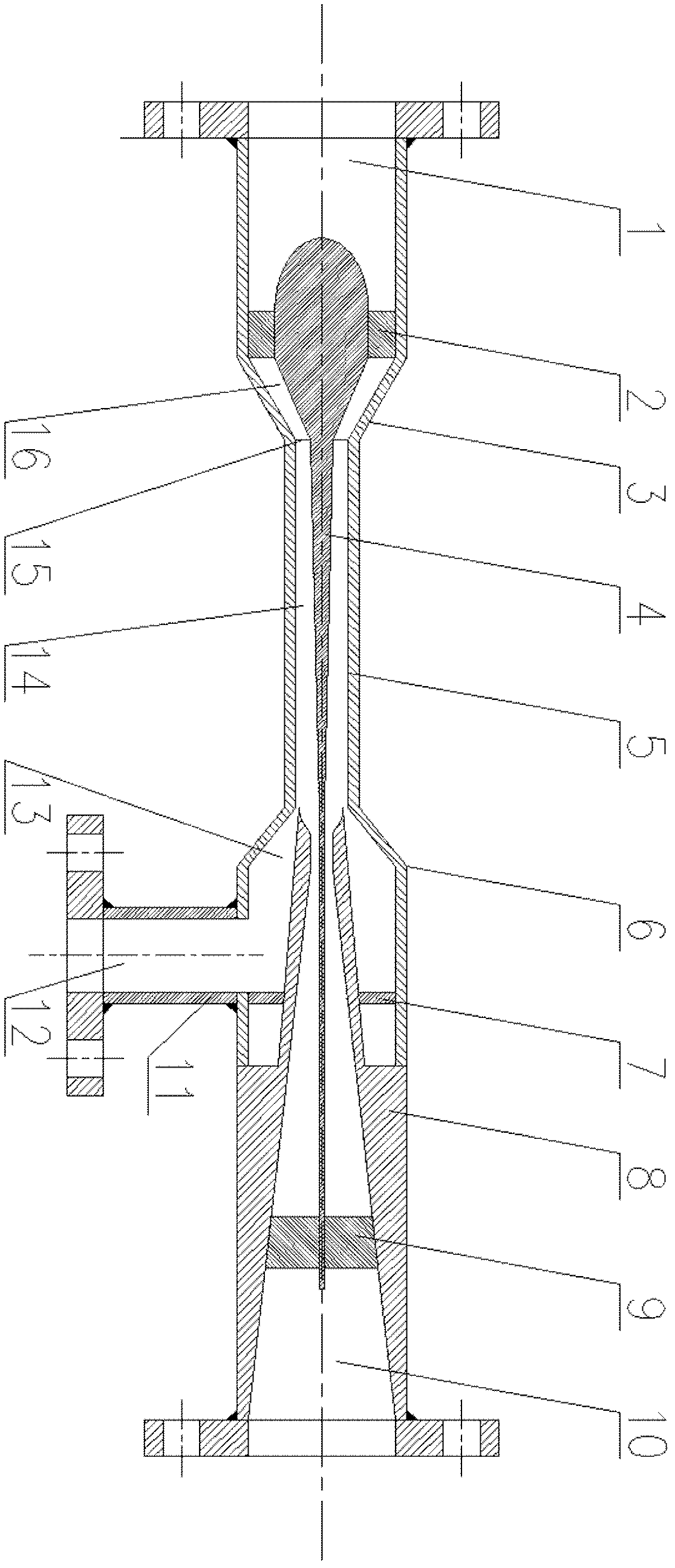
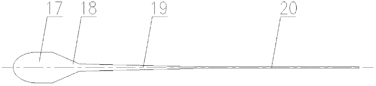
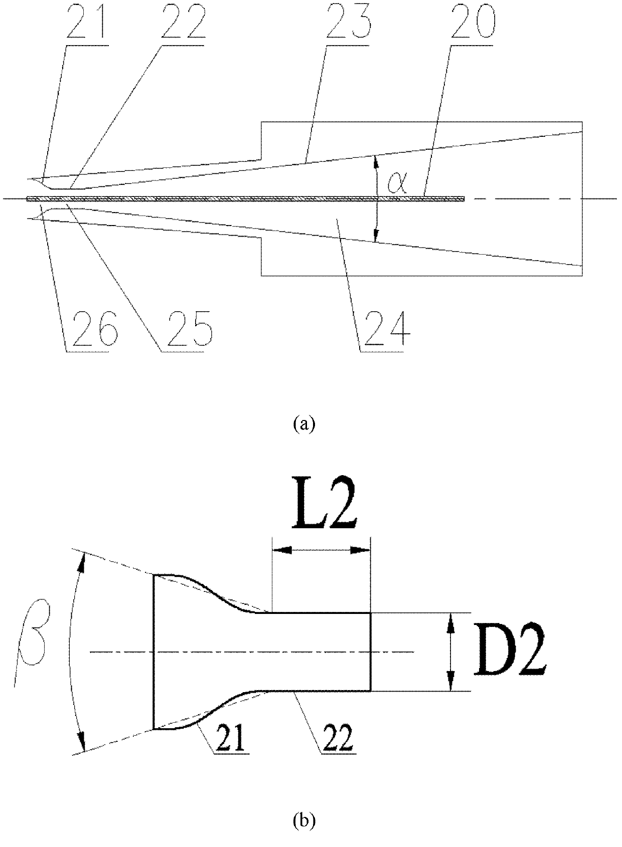
[0017] see figure 1 . Composed of liquid pipe 11, dry gas outlet 10 and liquid outlet 12; central body 4 includes initial section 17, constriction cone section 18, tapering cone section 19 and cylindrical section 20, constriction section 3 and constriction cone section 18 form a subsonic constriction flow Road 16, the outer straight pipe section 5 and the tapered tapered section 19 form a supersonic swirl separation flow channel 14, and the junction of the subsonic constriction flow channel 16 and the supersonic swirl separation flow channel 14 constitutes the first throat 15, the first throat The area of ​​15 is A t1 The back pressure section 8 includes a second contraction section 21, a second throat 22 and a second expansion section 23, and forms a supersonic compression flow channel 26, a second throat flow channe...


PUM


Abstract

The invention relates to a double-throat-type gas supersonic velocity cyclone separating device and is applied to the fields of multi-component gas mixture separation, and the like. A gas flows by a plurality of blade lattices in an inlet section and rotates, thereby sequentially entering into a subsonic velocity contracting channel, a first throat runner and a supersonic velocity cyclone separating runner in a cyclone manner; the airflow is expanded and reaches a supersonic velocity, thereby forming a low temperature and a low pressure and condensing the water in the gas or the water and heavy hydrocarbon component in natural gas; condensed liquid drops are thrown toward a wall surface under the effect of a huge centrifugal force generated by the rotation of airflow and are discharged from a liquid accommodating chamber, thereby efficiently realizing gas-liquid separation; a supersonic velocity compressing runner, a second throat runner and a second pressure expanding runner are arranged behind the supersonic velocity cyclone separating runner; according to the design, an impact wave can be fixed in the second throat runner, thereby limiting the disturbance caused by the impact wave, reducing the influence of backpressure on an impact wave position and causing the upstream supersonic velocity flow to be more stable; and a boundary layer separation effect caused by the impact wave can be avoided, the frictional resistance loss can be reduced and the backpressure capability of the separating device can be promoted.

Description

Technical field: [0001] The invention relates to a double-throat gas supersonic cyclone separation device, which belongs to the technical field of low-temperature condensation and cyclone separation of multi-component mixed gas. Background technique: [0002] Natural gas dehydration and heavy hydrocarbon separation are important processes in oil and gas gathering and transportation systems. Traditional treatment methods usually adopt methods such as vapor compression refrigeration, throttling expansion refrigeration, and expander refrigeration to obtain cooling capacity to achieve low-temperature separation. If necessary, heating or adding hydrate inhibitors is required to prevent hydrate crystallization from freezing and blocking pipelines and equipment. The system efficiency is low, energy is wasted, and the process is extremely complicated, costly, requires huge equipment, and the cost and operating expenses are very high. Supersonic cyclone separation technology is a ne...

Claims


Application Information

Patent Timeline
Patent Type & Authority Patents(China)
IPC IPC(8): B01D53/24B01D45/16B01D5/00E21B43/34
Inventor 文闯曹学文杨燕
Owner 文闯
Features
  • R&D
  • Intellectual Property
  • Life Sciences
  • Materials
  • Tech Scout
  • Unparalleled Data Quality
  • Higher Quality Content
  • 60% Fewer Hallucinations
Learn More