Battery wheel capable of being rapidly disassembled and assembled with bare hand
A free-hand speed and battery technology, which is applied in the field of battery wheels that can be disassembled and assembled with bare hands to achieve the effect of saving battery space, lowering the center of gravity of the whole vehicle, and reducing the weight of the whole vehicle
- Summary
- Abstract
- Description
- Claims
- Application Information
AI Technical Summary
Problems solved by technology
Method used
Image
Examples
Embodiment 1
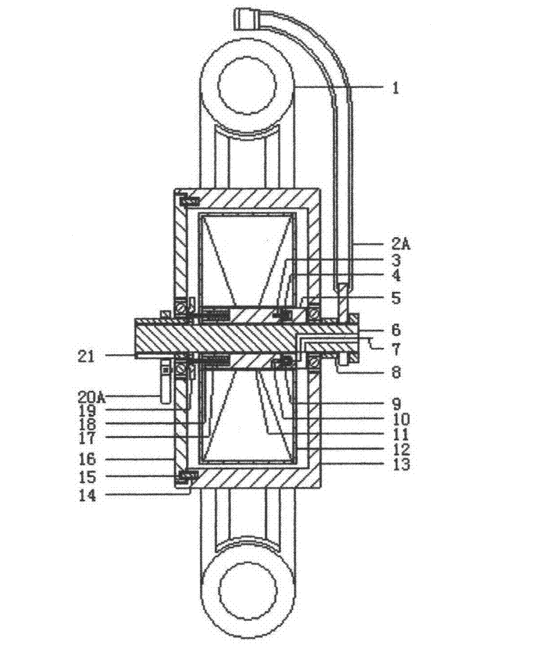
[0009] Embodiment one: see attachment figure 1 , attached Figure 5 , attached Figure 7 , attached Figure 9 , attached Figure 10 , the center right shaft section of the wheel shaft 6 has an axial through hole, and the shaft section at the lower part of the axial through hole or at the lower part of the interruption has a radial groove or a radial slot hole, and the diameters of the axial through hole and the radial slot hole depend on The wire diameter of the lead wire required by the battery capacity, the right part of the middle section of the wheel shaft 6 is fixedly sleeved on the plastic half-groove 5 with threads, and the left part is looped on the non-groove 11 with the same quality and similar shape as the half-groove 5, The two can be that the inside and outside are round tube faces, and the inside face can also be round tube faces and the outside is four sides, five sides, six sides, eight sides, and the lower right part of the half groove wheel 5 is a half no...
Embodiment 2
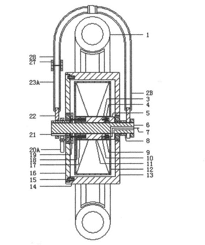
[0010] Embodiment two: see attachment figure 2 , attached Figure 5 , attached Image 6 , attached Figure 7 , attached Figure 9 , attached Figure 10 , the wheel shaft 6 between the shaft sleeve tube ring 8 and the nut is fastened to the auxiliary arm fork 2B, the section seam shaft 21 set on the left side of the hub cover 16 is set on the single quick release 20A from right to left, and is fixed on the fork collar 22. The upper part of the fork collar 22 is preferably fixed in the pipe at the lower end of the seamless fork tube 20A by welding, and the section seam sleeve 21 is fixedly sleeved on the fork collar 22 with threads. The diameter of the seamless fork tube 20A is the same as that of the auxiliary The arms 28 are the same, and the port sections at the opposite places have external threads and are screwed on the sleeve arm pipe 27 with internal threads. When disassembling, the sleeve arm pipe 27 needs to be screwed to separate the seamless fork pipe 23 from th...
Embodiment 3
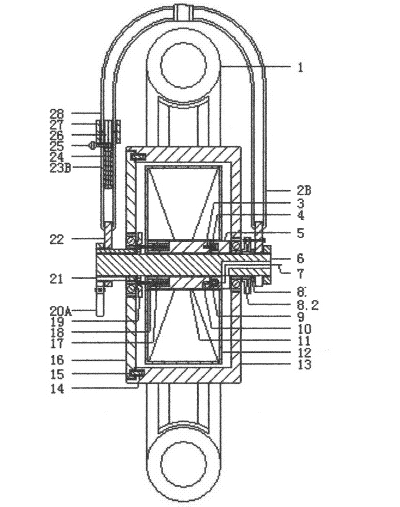
[0011] Embodiment three: see attachment image 3 , attached Figure 5 , attached Image 6 , attached Figure 7 , attached Figure 9 , attached Figure 10 The wheel shaft 6 between the bearing of the hub disc 13 and the shaft sleeve tube ring 8 is installed with a brake drum 8.2, the wheel shaft 6 between the shaft sleeve tube ring 8 and the nut is fastened to the auxiliary arm fork 2B, and the left end of the brake drum 8.2 is connected to the bearing On the outer ring side of the right end, the fixed lining on the right is fixed to the fork liner of the auxiliary arm fork 2B with screws, and the hub cover 16 is fixedly sleeved on the fork shaft ring 22 from right to left by the segmental sleeve 21 on the left. The single quick release 21A, the upper part of the fork collar 22 is fixedly placed in the tube at the lower end of the section seam fork pipe 23B by welding, and a bolt spring 24 and a bolt post 26 are installed in the pipe of the section seam fork pipe 23B. A bo...
PUM
 Abstract
Description
Claims
Application Information
 - R&D
- Intellectual Property
- Life Sciences
- Materials
- Tech Scout
- Unparalleled Data Quality
- Higher Quality Content
- 60% Fewer Hallucinations
Browse by: Latest US Patents, China's latest patents, Technical Efficacy Thesaurus, Application Domain, Technology Topic, Popular Technical Reports.
© 2025 PatSnap. All rights reserved.Legal|Privacy policy|Modern Slavery Act Transparency Statement|Sitemap|About US| Contact US: help@patsnap.com


