Multichannel synchronous filling device of liquid filling machine

A filling device and filling machine technology, applied in liquid bottling, liquid filling, liquid treatment, etc., can solve the problems of waste of filling materials, high operating costs, and large power consumption, so as to save filling materials and avoid accidental damage , The effect of low power consumption

Inactive Publication Date: 2012-04-11
常州市金坛新鑫包装机械有限公司
View PDF8 Cites 5 Cited by
  • Summary
  • Abstract
  • Description
  • Claims
  • Application Information

AI Technical Summary

Problems solved by technology

[0002] Most of the existing vertical liquid filling machines use piston-type filling cylinders to achieve filling. Among them, the filling cylinders are usually driven by air pressure, that is, the cylinder drives the piston in the filling cylinder to twitch back and forth to realize the filling of liquid materials. Filling, but due to the existence of pneumatic filling filling machines ① single filling speed, when the filling volume is close to full, the filled liquid is prone to foam overflowing from the mouth of the bottle, to overcome this shortcoming can only be reduced filling speed, so that The filling efficiency is low, and the production capacity of the whole machine cannot be brought into play
②The filling accuracy is not high. Since the pneumatic filling machine uses pressure gas as the power source, and the gas has compressible characteristics, when the air pressure fluctuates greatly, the cylinder piston detects the piston signal from the magnetic switch during the forward process. When the solenoid valve changes direction, the entire return stroke of the piston will change, resulting in a change in the filling dose, which will affect the stability of the filling dose.
③When adjusting the filling dose, each filling cylinder must be adjusted one by one, which is not only troublesome to debug, but also wastes a lot of filling materials. For multi-head filling machines, the adjustment time is longer and more troublesome
[0005] ①Because all the filling cylinders are installed on the upper fixed plate, and the piston rod is fixed on the lifting plate, when the liquid in the filling

Method used


Image

  • Multichannel synchronous filling device of liquid filling machine
  • Multichannel synchronous filling device of liquid filling machine
  • Multichannel synchronous filling device of liquid filling machine

Examples


Embodiment 1

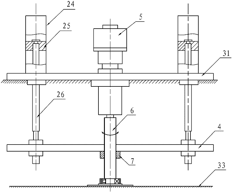
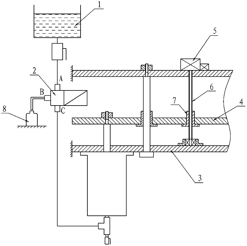
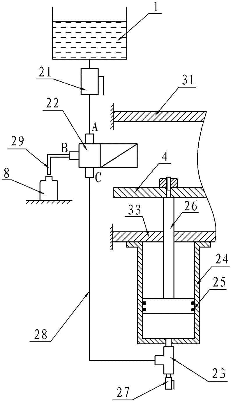
[0026]Embodiment 1: A multi-head synchronous filling device for a liquid filling machine, including a liquid storage tank 1, sixteen filling units 2, a fixed frame 3, a lifting plate 4, a servo motor 5, a ball screw 6 and a screw nut Cover 7, the liquid storage tank 1 and the fixed frame 3 are all fixed on the frame, and the liquid storage tank 1 is located above the fixed frame 3, and the fixed frame 3 is composed of an upper fixed plate 31, a guide rod 32 and a lower fixed plate 33 , the upper fixed plate 31 and the lower fixed plate 33 are fixedly connected into a frame body by four guide rods 32 intervals; the lifting plate 4 is located between the upper fixed plate 31 and the lower fixed plate 33, and four There are only guide sleeves 41, and the lifting plate 4 is set on the guide rod 32 through four guide sleeves 41. The cooperation between the guide sleeve 41 and the guide rod 32 is a precision clearance fit; the servo motor 5 is fixed on the upper fixing plate 31, and ...


PUM


Abstract

The invention relates to a multichannel synchronous filling device of a liquid filling machine, which comprises a liquid storage bath, a filling unit, a mount, a lifter plate, a servo motor, a ball screw and a screw-nut sleeve. the servo motor is fixed on a fixed plate of the mount, the screw-nut sleeve is fixed on the lifter plate and is in screwed fit with the ball screw; in the filling unit, a filling cylinder is in ceiling mounting, the body of a cylinder sleeve towards downward, a piston rod towards downward, a three-way connection is provided on the lower end face of the filling cylinder, a three-way valve is connected between the liquid storage bath and the three-way connection through a flexible pipe, the discharge hatch of the three-way valve is connected with a filling nozzle. The structure of the invention has no bubbling and draining phenomena, and is capable of saving the filled raw materials, and avoiding accident damage on operators caused by the leakage of the materials, the filling machine can reach maintenance-free requirement. The power consumption for driving lifting is low, so that the energy and the cost can be saved. The product type can be replaced in a convenient and fast mode, so that the user requirement can be satisfied.

Description

Technical field: [0001] The invention relates to a vertical liquid filling machine, in particular to a vertical piston type constant volume liquid filling machine. Background technique: [0002] Most of the existing vertical liquid filling machines use piston-type filling cylinders to achieve filling. Among them, the filling cylinders are usually driven by air pressure, that is, the cylinder drives the piston in the filling cylinder to twitch back and forth to realize the filling of liquid materials. Filling, but due to the existence of pneumatic filling filling machines ① single filling speed, when the filling volume is close to full, the filled liquid is prone to foam overflowing from the mouth of the bottle, to overcome this shortcoming can only be reduced filling speed, so that The filling efficiency is low, and the production capacity of the whole machine cannot be brought into play. ②The filling accuracy is not high. Since the pneumatic filling machine uses pressure g...

Claims


Application Information

Patent Timeline
IPC IPC(8): B67C3/02B67C3/26
Inventor 何新华
Owner 常州市金坛新鑫包装机械有限公司
Why Eureka
Try Eureka