Supercharge Your Innovation With Domain-Expert AI Agents!

Method for detecting micro-arc oxidation arcing characteristics of alloy by using anodic polarization curve

A technology of anodic polarization and micro-arc oxidation, applied in electrolysis process, electroforming, etc., can solve the problems of large workload, waste of electric energy and solution raw materials, etc.

Active Publication Date: 2012-04-11
HARBIN INST OF TECH
View PDF2 Cites 1 Cited by
  • Summary
  • Abstract
  • Description
  • Claims
  • Application Information

AI Technical Summary

Problems solved by technology

[0004] The present invention aims to solve the technical problems of large workload, waste of electric energy and solution raw materials caused by the existing method of using the micro-arc oxidation experiment process to verify the influence of the type and amount of additives in the electrolyte on the arc-starting characteristics of the micro-arc oxidation. To provide a method for detecting arcing characteristics of alloy micro-arc oxidation by using anodic polarization curve

Method used


Image

  • Method for detecting micro-arc oxidation arcing characteristics of alloy by using anodic polarization curve
  • Method for detecting micro-arc oxidation arcing characteristics of alloy by using anodic polarization curve
  • Method for detecting micro-arc oxidation arcing characteristics of alloy by using anodic polarization curve

Examples


specific Embodiment approach 1

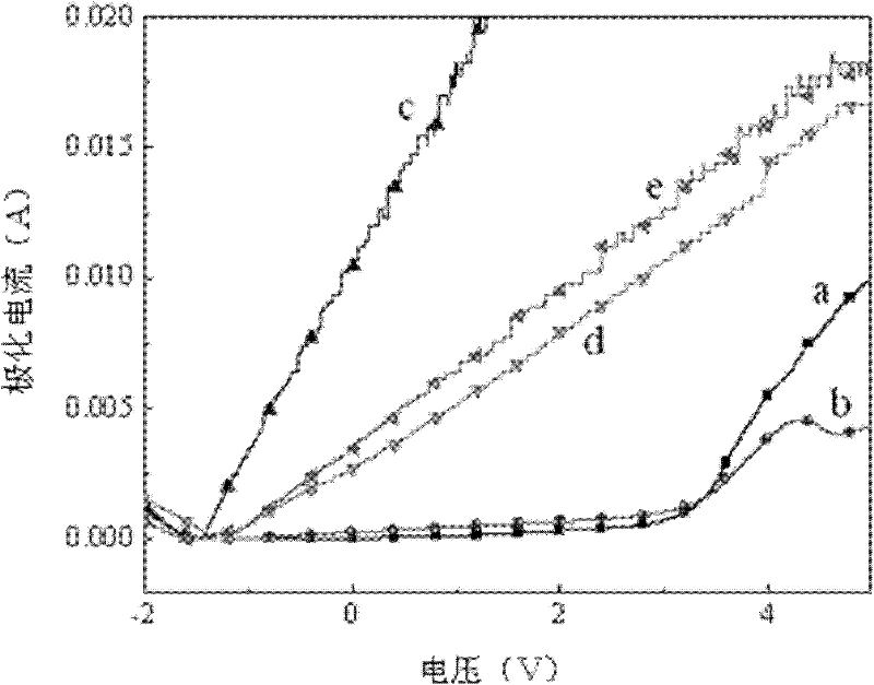
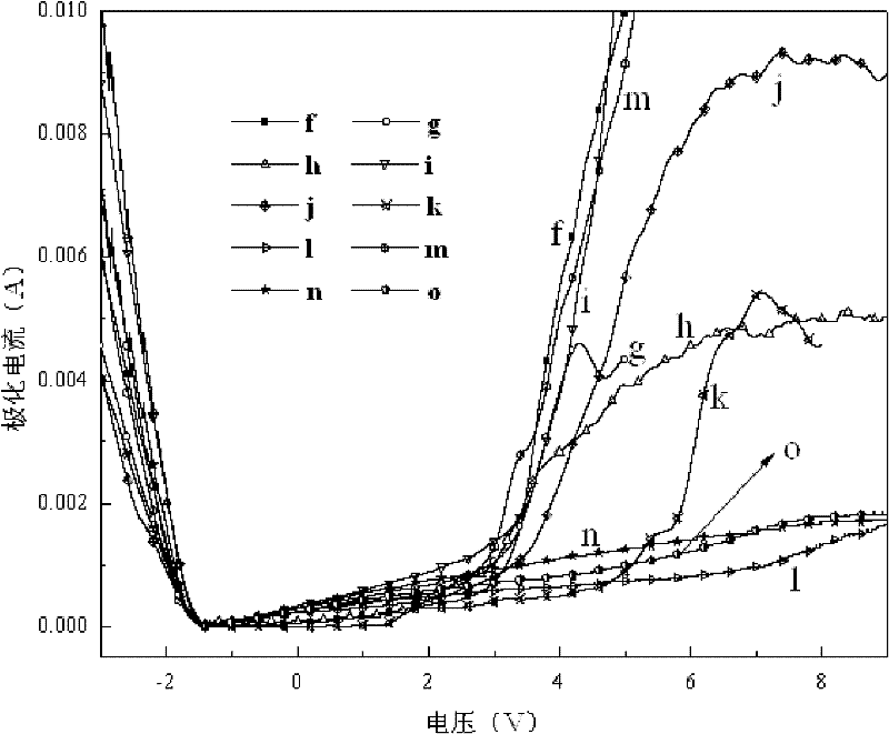
[0015] Specific implementation mode 1: The method for detecting the arcing characteristics of alloy micro-arc oxidation by using the anodic polarization curve in this embodiment is carried out according to the following steps:

[0016] 1. Prepare the electrolyte to be verified;

[0017] Two, measure the anodic polarization curve with the voltage U as the abscissa and the current I as the ordinate in the electrolytic solution to be verified obtained in step 1;

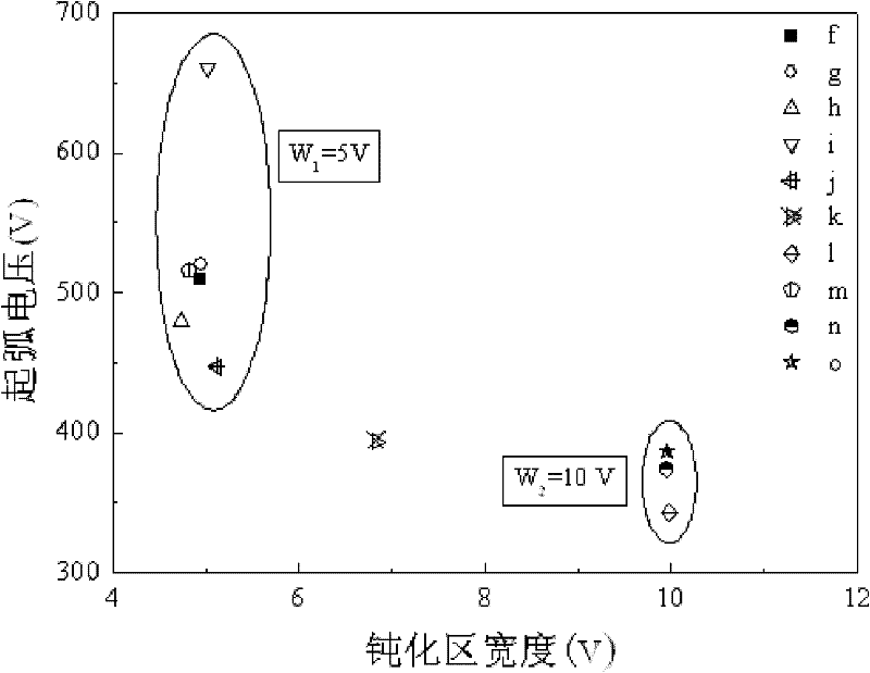
[0018] 3. On the anodic polarization curve measured in step 2, if there is no passivation zone, the alloy cannot undergo micro-arc oxidation in the electrolyte; if there is a passivation zone, the alloy can undergo micro-arc oxidation in the electrolyte Arc oxidation; the wider the passivation interval, the lower the voltage of the alloy in the electrolyte for micro-arc oxidation arc discharge; when the passivation interval is similar, the polarization current on the anodic polarization curve before the passivation film...

specific Embodiment approach 2

[0020] Embodiment 2: This embodiment differs from Embodiment 1 in that the alloy in step 2 is magnesium alloy, aluminum alloy or titanium alloy. Others are the same as in the first embodiment.

specific Embodiment approach 3

[0021] Embodiment 3: The difference between this embodiment and Embodiment 1 or 2 is that the anodic polarization curve in step 2 is measured by a potentiostatic method. Others are the same as in the first or second embodiment.


PUM


Abstract

The invention discloses a method for detecting micro-arc oxidation arcing characteristics of an alloy by using an anodic polarization curve, and relates to a micro-arc oxidation method for the alloy, which aims to solved the technical problems of high working amount and waste of electric energy and solution raw materials caused by the conventional method for verifying influences of types and using amount of additives in an electrolyte solution on the micro-arc oxidation arcing characteristics by using a micro-arc oxidation experiment process. The method comprises the following steps of: measuring the anodic polarization curve, which uses voltage U as a horizontal ordinate and current I as a vertical coordinate, of the alloy in an electrolyte solution to be verified; judging whether micro-arc oxidation can be performed or not due to the existence of a passivation area; determining micro-arc oxidation arcing discharging voltage of the alloy in the electrolyte solution according to widths of passivation intervals; and when the widths of the passivation intervals are approximate to one another, determining the micro-arc oxidation arcing discharging voltage of the alloy in the electrolyte solution according to polarization current of a passivation film before destabilization. By the method, energy sources are saved for a low-voltage low-current-density process; and the method can be used for predicting the micro-arc oxidation arcing characteristics of the alloy.

Description

technical field [0001] The invention relates to a method for alloy micro-arc oxidation. Background technique [0002] Magnesium alloys are used in industrial fields such as aviation, automobiles and electronic communications due to their advantages such as low density, high specific strength and specific stiffness, and good electromagnetic shielding. However, due to the active chemical properties of magnesium, it is very easy to oxidize, and a loose and porous oxide film is formed on the surface. The oxide film has poor protection ability for the substrate and is not suitable for use in most corrosive environments. Applications. Micro-arc oxidation is a surface modification technology developed on the basis of anodic oxidation. This technology is to place metals such as magnesium, aluminum, titanium or their alloys in the electrolyte, under high temperature and high pressure, thermochemistry, plasma chemistry and The method of generating spark discharge on the surface of t...

Claims


Application Information

Patent Timeline
Patent Type & Authority Applications(China)
IPC IPC(8): C25D1/02
Inventor 田修波王晓波巩春志杨士勤
Owner HARBIN INST OF TECH
Features
  • R&D
  • Intellectual Property
  • Life Sciences
  • Materials
  • Tech Scout
  • Unparalleled Data Quality
  • Higher Quality Content
  • 60% Fewer Hallucinations
Learn More