Fast lifting slip form

A sliding form and formwork technology, which is applied in the field preparation of formwork/formwork/work frame, building components, construction, etc., can solve problems such as cold joints, unguaranteed construction progress, and long time for slipping formwork to achieve The effect of speeding up the construction progress, solving the quality and progress problems of building construction, and shortening the construction period of concrete forming construction

Inactive Publication Date: 2013-08-14
边海波
View PDF6 Cites 0 Cited by
  • Summary
  • Abstract
  • Description
  • Claims
  • Application Information

AI Technical Summary

Problems solved by technology

[0003] At present, the main technical problem in slip form construction is how to accurately grasp the timing of formwork lifting, which is a key link that affects construction quality and construction progress
If the timing of the formwork sliding is early, the concrete layer just out of the formwork will have low plasticity loss, poor plasticity, easy deformation, or even collapse. If the timing of the formwork sliding is late, the concrete will be excessively solidified and stick to the formwork, resulting in the formwork being unable to slide up , or cause the upper layer to solidify and form cold seams, especially in low temperature climates, this technical problem is more prominent; another technical problem is that it takes a long time to wait for the forming of the sliding mold, the construction speed is slow, and the construction progress cannot be guaranteed
[0004] In addition, the technical understanding of using steam to speed up the curing and hardening of concrete is getting deeper and wider, and the application is becoming more and more extensive. However, most of the existing steam curing technologies are only for independent building components, and there is no steam curing combined with a sliding form mechanism. mechanism

Method used


Image

  • Fast lifting slip form
  • Fast lifting slip form
  • Fast lifting slip form

Examples


Embodiment Construction

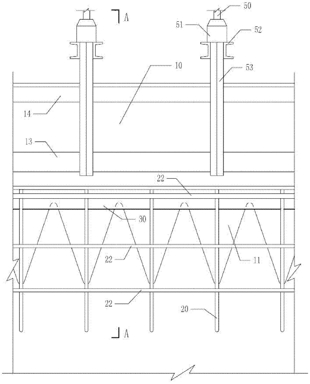
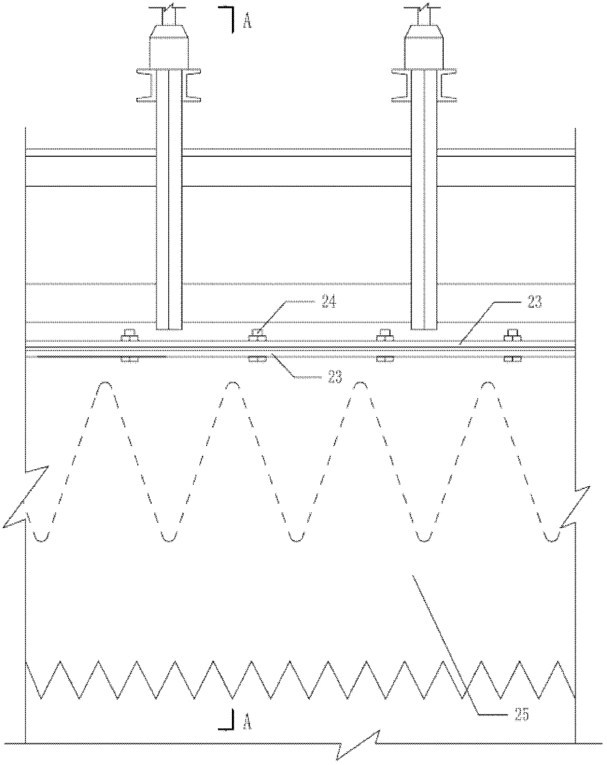
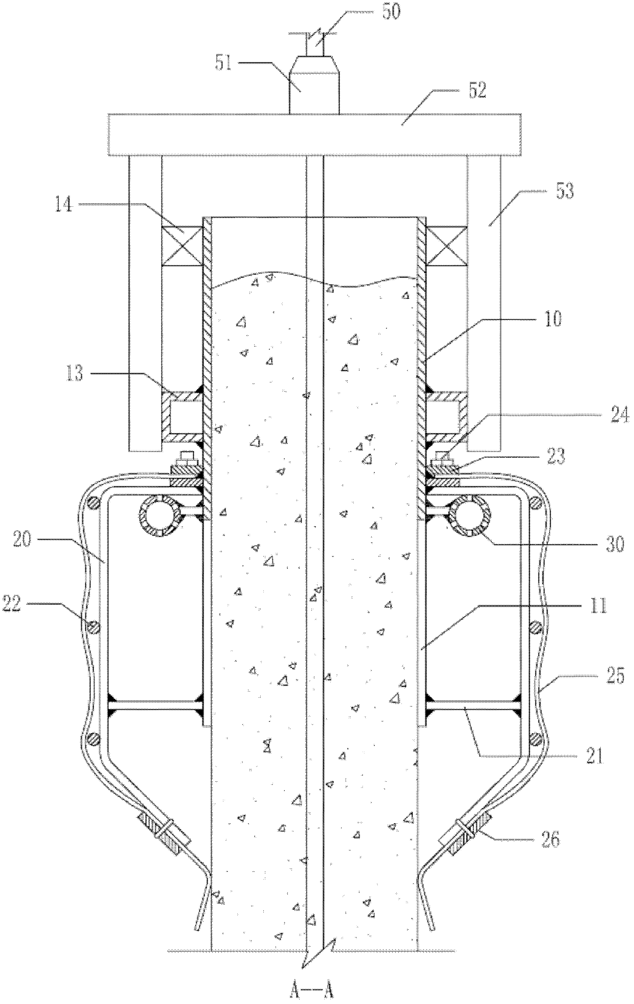
[0014] The rapid lifting sliding form disclosed in the patent application of the present invention includes a formwork, a formwork enclosure and a formwork gantry sliding mechanism, and the formwork is composed of a molded enclosure 10 and a toothed molded enclosure 11 at the bottom of the molded enclosure 10 , it can be integrally made into a formwork with a lower tooth-shaped edge from a piece of coaming material, or a tooth-shaped molded coaming 11 can be fixedly welded under the original rectangular formwork 10, and the tooth shape of the tooth-shaped molded coaming 11 Such as Figure 5 As shown, it can be the wavy shape of the figure (a), the zigzag shape of the figure (c), or the deformed figure (b) based on the figure (c). The tooth shape of the figure (b) is equivalent to the adjacent An extension distance is added between the sawtooth shapes, and the tooth shape can also be other set sinusoidal waveforms and the like. The outer surface of the molded enclosure 10 is f...


PUM


Abstract

The invention provides a fast lifting slip form, comprising a formwork, a formwork enclosure ring and a formwork gantry climbing mechanism, wherein the formwork comprises a molding enclosure plate and a toothed molding enclosure plate at the lower part of the molding enclosure plate; and the gantry vertical beam of the formwork gantry climbing mechanism is fixedly connected with the molding enclosure plate or the molding enclosure ring. In the technical scheme provided by the invention, the toothed molding enclosure plate is adopted at the lower part of the formwork, so that obvious deformation is not caused in the whole climbing distance bedding surface of a slip plate, the technical problem of large-area collapse is not easily caused, especially after the combination of the toothed molding enclosure plate structure with a steam curing structure, on the premise of ensuring construction quality, the construction progress is accelerated, therefore the building construction quality and progress problems are solved under low-temperature weather conditions.

Description

technical field [0001] The patent application of the present invention relates to a sliding form device for implementing concrete cast-in-place forming construction construction projects. Background technique [0002] Sliding form is a forming mold assembly mechanism used in cast-in-place concrete building construction. It mainly includes forming formwork, formwork enclosure, formwork door frame sliding mechanism, and the gap between two formworks, or between formwork and the foundation wall. Concrete is poured in layers from bottom to top in the sleeve groove. After the lower concrete in the sleeve groove reaches the condensation degree required by the technology, the whole set of sliding form slides up and moves up. Complete building molding construction. The templates in the existing sliding form are all rectangular slabs, and the technical requirement is that the template should be lifted when the lower poured concrete in the groove has not lost its plasticity, so as to...

Claims


Application Information

Patent Timeline
Patent Type & Authority Patents(China)
IPC IPC(8): E04G11/22
Inventor 边海波杨树峰
Owner 边海波
Why Eureka
Try Eureka