
Manufacturing method for end socket module of quenching heat exchanger

A technology of quenching heat exchanger and manufacturing method, which is applied in the manufacturing field of the head module of the quenching heat exchanger, which can solve the problems of long order cycle, poor stress resistance of the head, shortening the operation cycle of the cracking furnace, etc., and achieve performance index improvement , stable performance, satisfying the effect of long-term operation

Active Publication Date: 2013-09-04
CHINA PETROLEUM & CHEM CORP +2
View PDF4 Cites 0 Cited by
  • Summary
  • Abstract
  • Description
  • Claims
  • Application Information

AI Technical Summary

Problems solved by technology

The quality of the head module of the quench heat exchanger is an important condition to ensure the operation cycle of the ethylene plant. The castable of the head module of the heat exchanger falls off, and the castable that falls off may block the radiant furnace tube, causing overheating of the furnace tube, shortening the operating cycle of the cracking furnace, and even forcing the cracking furnace to stop for emergency treatment; at the same time, the castable falls off, causing The outer wall of the head module of the quenching heat exchanger was overheated and burned, and the cracked gas was unevenly distributed in the quenching heat exchanger, resulting in serious coking of some heat exchange tubes and even scrapping
[0003] The head module of the quenching heat exchanger has been relying on imports before, which has the disadvantages of short service life, long order cycle, high price, etc., and high cost; and the existing head of the quenching heat exchanger has poor stress resistance, which affects the operating cycle. At the same time, its high temperature resistance and erosion resistance still need to be further improved.

Method used


Image

  • Manufacturing method for end socket module of quenching heat exchanger
  • Manufacturing method for end socket module of quenching heat exchanger
  • Manufacturing method for end socket module of quenching heat exchanger

Examples


Embodiment Construction

[0049] The present invention will be further described in detail below in conjunction with the accompanying drawings and embodiments.

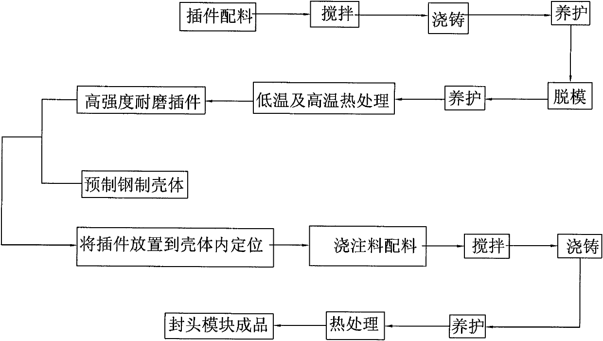
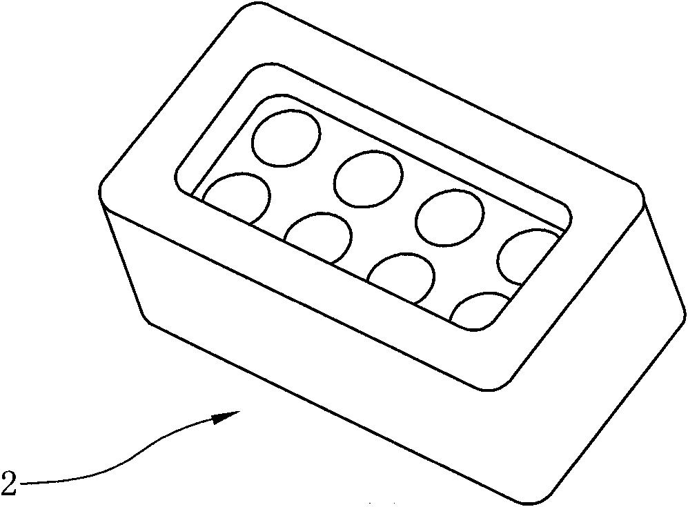
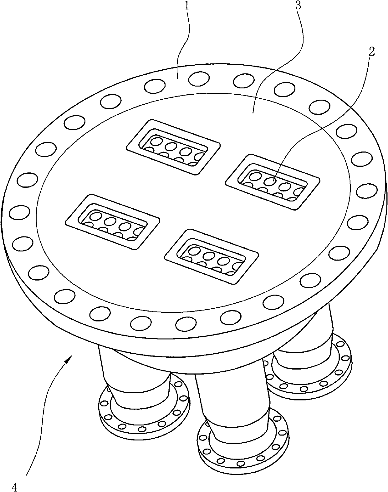
[0050] Such as figure 1 and figure 2 As shown, the manufacturing method of the quenching heat exchanger head module is as follows:

[0051] A) the steel housing 1 of the prefabricated quenching heat exchanger head module;

[0052] B) Prepare the materials used for the prefabricated insert 2 according to the following formula, and the materials used for the insert include base materials and ingredients.

[0053] Wherein, each component content in base material is weight content;

[0054]

[0055] The consumption of each component is based on the total amount of the base material in the batching, and its weight composition is as follows:

[0056]

[0057]

[0058] The consumption of each component in the batching is calculated according to the total amount of the filler base material.

[0059] Mix the base material and ingredients...


PUM


Abstract

The invention relates to a manufacturing method for an end socket module of a quenching heat exchanger. The manufacturing method comprises the following steps: A) prefabricating a steel shell of the end socket module of the quenching heat exchanger; B) utilizing specially researched formula and technology to prefabricate a plug-in piece of the end socket module of the quenching heat exchanger; C) preparing filling materials according to the specially researched formula, uniformly stirring the filling materials, and then pouring the filling materials into a clearance between the shell and the plug-in piece; and D) performing heat treatment on the end socket poured with the filling materials according to the special technology, thereby acquiring the end socket module of the quenching heat exchanger provided by the invention. Compared with the prior art, the end socket module of the quenching heat exchanger which is prepared according to the manufacturing method provided by the invention has the advantages that all items of performance indexes are greatly promoted, the performance is more stable, the service life is more than 2 times of the service life of the end socket module in the prior art, and the demand on the long periodic running of the quenching heat exchanger is met.

Description

technical field [0001] The invention relates to a method for manufacturing a sealing head module of a quenching heat exchanger. Background technique [0002] The quenching heat exchanger is the supporting equipment of the ethylene plant. After the pyrolysis gas is released from the cracking furnace radiation furnace tube after high temperature cracking in the cracking furnace, it is collected in the head module of the quenching heat exchanger and then redistributed, and then heat exchanged through the quenching heat exchanger. tube for heat exchange. The head of the quenching heat exchanger generally includes a steel shell, a high-strength wear-resistant core located in the shell, and fillers are filled between the shell and the core. The head module of the quenching heat exchanger needs to withstand the high-speed erosion of high-temperature gas at about 900 °C, and must have good thermal shock stability and heating line change rate. The quality of the head module of the ...

Claims


Application Information

Patent Timeline
Patent Type & Authority Patents(China)
IPC IPC(8): F28F9/00C04B28/06C04B35/185B28B1/14B28B11/24
Inventor 杨伟林潘永忠
Owner CHINA PETROLEUM & CHEM CORP
Learn More