Method and system for realizing subsynchronous resonant control

A technology of sub-synchronization and energy storage equipment, applied in the field of power control, can solve the problems of reduced sub-synchronous modal damping of units, deterioration of sub-synchronous resonance of the system, affecting the safe and stable operation of units and power grids, etc., so as to reduce unit operation risks and improve The effect of running stability

Active Publication Date: 2012-04-11
北京睿能世纪科技有限公司
View PDF3 Cites 10 Cited by
  • Summary
  • Abstract
  • Description
  • Claims
  • Application Information

AI Technical Summary

Problems solved by technology

[0003] However, with the increase of long-distance large-capacity transmission lines, in order to improve the transmission capacity and system stability of long-distance transmission, more and more power grids use high-speed control devices based on power electronics technology such as fixed series capacitor compensation and high-voltage direct current transmission. Under certain conditions, this type of device may cause subsynchronous oscillation of the system, resulting in vibration of the shaft system of the unit, affecting the life of the unit, and even more likely to affect the safe and stable operation of the unit and the power grid.
At the same time, because the energy storage system participates in the AGC or frequency modulation application at the generator end, it essentially changes the original dynamic response characteristics of the generator set. Under certain conditions, the connection of the energy storage system will cause the sub-synchronous modal damping of the unit In extreme cases, when the energy storage system responds to AGC commands or frequency modulation dispatching commands, it may inject sub-synchronous mode excitation current into the power grid to excite sub-synchronous resonance of the unit

Method used


Image

  • Method and system for realizing subsynchronous resonant control
  • Method and system for realizing subsynchronous resonant control
  • Method and system for realizing subsynchronous resonant control

Examples


Embodiment Construction

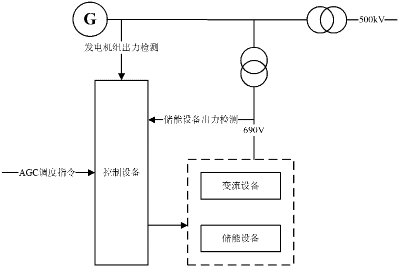
[0021] The method and system for realizing sub-synchronous resonance control in the embodiments of the present invention are mainly applied in power control systems including energy storage devices, such as figure 1 As shown, the power control system mainly includes energy storage equipment, converter equipment and control equipment; among them,

[0022] The energy storage device is the energy storage unit of the system, and at the same time provides DC bus voltage support for the converter device to ensure that the grid-connected operation requirements of the converter device are met; the converter device controls the energy interaction between the power grid and the energy storage device, According to the power command output by the control device, it actually generates and controls the amplitude and phase of the energy storage device injecting or drawing current into the grid; the control device receives the AGC scheduling through the peripheral RTU (Remote Terminal Unit, re...


PUM


Abstract

The embodiment of the invention discloses a method and a system for realizing subsynchronous resonant control. By adoption of the method and the system, grid current control is realized by detecting a machine-end voltage signal of a generating set, extracting a subsynchronous resonance mode component from the machine-end voltage signal, generating the damping current reference quantity, superimposing the damping current reference quantity with an automatic generation control (AGC) power command, and outputting the damping current reference quantity superimposed with the AGC power command to converter equipment. Because the converter equipment can control and generate actual subsynchronous mode damping current to ensure that the damp of a system in subsynchronous resonance mode is positive, so that the influence on the stability of the generating set in the subsynchronous mode caused by the running of energy storage equipment is avoided, and the functions of improving the running stability of the energy storage equipment and an electric power system and effectively reducing the running risk of the generating set can be achieved.

Description

technical field [0001] The present invention relates to the technical field of electric power control, and more specifically relates to a method and a system for realizing unit subsynchronous resonance control in the application of AGC (Automatic Generation Control, automatic generation control) or frequency modulation at the generator end by an energy storage system. Background technique [0002] At present, the power system mainly includes the power grid, generators that provide electrical energy, and various electrical equipment. Among them, in order to ensure the stable and reliable operation of the entire power system, it is required that the electrical energy provided by the generator and the electrical energy consumed by electrical equipment be balanced in real time. For this reason, the existing technology connects the energy storage system in parallel at the generator end, utilizes the fast and accurate response characteristics of the energy storage system to the pow...

Claims


Application Information

Patent Timeline
Patent Type & Authority Applications(China)
IPC IPC(8): H02J3/28
Inventor 薛飞王澍牟镠峰
Owner 北京睿能世纪科技有限公司
Why Eureka
Try Eureka