Compensation control circuit and method for direct current converter

A DC converter, compensation control technology, applied in electrical components, output power conversion devices, etc., can solve problems such as sub-harmonic oscillation, achieve fast dynamic response, ensure dynamic response, and not easy to oscillate.

Inactive Publication Date: 2012-04-11
SILERGY SEMICON TECH (HANGZHOU) CO LTD
View PDF6 Cites 28 Cited by
  • Summary
  • Abstract
  • Description
  • Claims
  • Application Information

AI Technical Summary

Problems solved by technology

[0007] In view of this, the present invention provides a compensation control circuit and method for a DC converter, which samples the inductor current in the main circuit while adding slope compensation, so as to solve the problem that the system is prone to sub-harmonic oscillation and improve the stability margin. quantity

Method used


Image

  • Compensation control circuit and method for direct current converter
  • Compensation control circuit and method for direct current converter
  • Compensation control circuit and method for direct current converter

Examples


Embodiment 1

[0046] refer to Figure 4 , which is a schematic structural diagram of the first embodiment of the compensation control circuit of the DC converter according to the present invention; the topology structure of the main circuit is a step-down DC converter as an example for illustration, the compensation control circuit of the DC converter include:

[0047] output voltage feedback circuit, which receives the output voltage of the main circuit V o , and output an output voltage feedback signal FB;

[0048] an inductor current sampling circuit, which samples the inductor current in the main circuit to output a sampled current signal;

[0049] The slope signal generating circuit generates a slope signal;

[0050] The first control unit receives the output voltage feedback signal FB, the signal obtained by adding the sampling current signal and the ramp signal, and the first reference voltage signal V ref1 , and compare to output the first control signal;

[0051] A second cont...

Embodiment 2

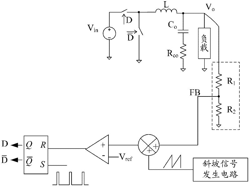
[0056] refer to Figure 5 , is a schematic structural diagram of a compensation control circuit for a DC converter provided by the present invention, where the topology of the main circuit is still a step-down DC converter as an example for illustration.

[0057] The output voltage feedback circuit described in this embodiment includes a resistor R 1 and R 2 The voltage divider circuit composed of series, the output voltage V of the main circuit o After the voltage is divided by the voltage divider circuit, the resistor R 1 and R 2 The common connection point of the outputs an output voltage feedback signal FB.

[0058] The inductor current sampling circuit can perform analog sampling on a fixed time period in the rising stage or falling stage of the inductor current in each switching cycle, and can also perform analog sampling on a fixed time period in the rising stage or falling stage of the inductor current in each switching cycle Points for digital sampling, which can...

Embodiment 3

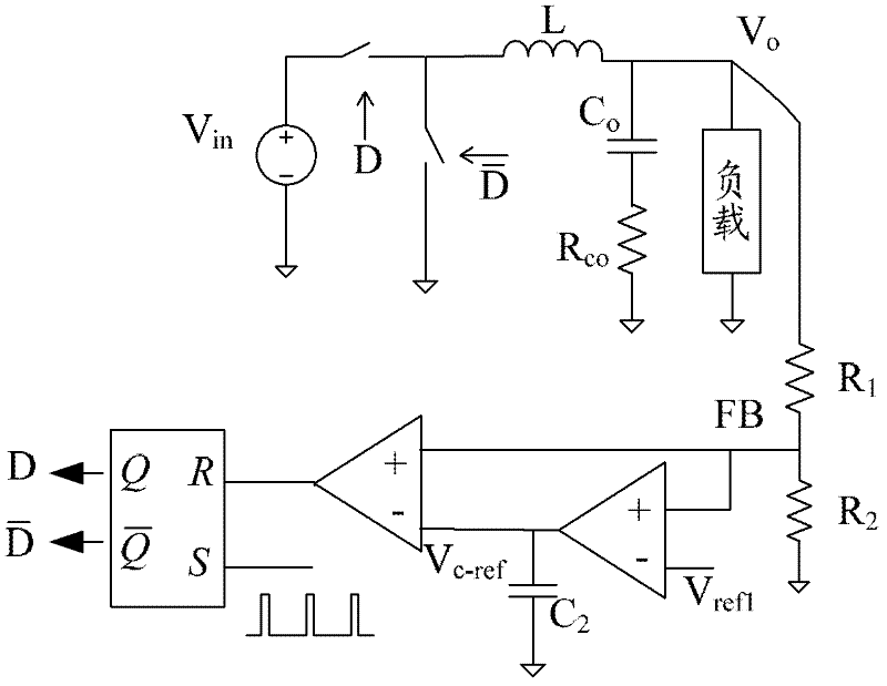
[0065] Figure 5 In the illustrated embodiment the first reference voltage signal V ref1 For a preset reference voltage signal, it is also possible to use Figure 7 The structure in the shown embodiment: the output voltage feedback signal FB and a preset reference voltage signal V ref2 The compared error amplification signal is passed through the capacitor C 2 The reference voltage signal V obtained after compensation c-ref as the first reference voltage signal.


PUM


Abstract

The invention discloses a compensation control circuit and method for a direct current converter. The compensation control circuit comprises an output voltage feedback circuit, an inductance current sampling circuit, a ramp signal generating circuit, a first control unit, a second control unit and a switch signal generating circuit, wherein the output voltage feedback circuit is used for outputting an output voltage feedback signal; the inductance current sampling circuit is used for sampling inductance current in a main circuit and outputting a sampling current signal; the ramp signal generating circuit is used for generating a ramp signal; the first control unit is used for receiving an output voltage feedback signal, a signal acquired by adding the sampling current signal with the ramp signal, and a standard voltage signal, and comparing to output a first control signal; the second control unit is used for outputting a second control signal for controlling the direct current converter to work in a variable-frequency or constant-frequency mode; and switch signal generating circuit is used for receiving a first control signal and a second control signal to output a switch control signal of a switch tube in the output main circuit. Due to the adoption of the compensation control circuit provided by the invention, the system can be kept in the stable state, and the stable allowance and response speed are increased.

Description

technical field [0001] The invention belongs to the technical field of DC switching power supplies, and in particular relates to a compensation control circuit and method for a DC converter. Background technique [0002] A DC converter is a converter that converts DC power into another or more DC power, and is the main component of a DC switching power supply. With the rapid development of power electronics technology, DC switching power supplies with DC converters as the core are more and more widely used. DC converters include buck DC converters, boost DC converters, buck-boost DC converters and flyback DC converters and other topologies. [0003] refer to figure 1 , figure 1 It is a schematic structural diagram of a control circuit of a common step-down DC converter in the prior art. R in the figure 1 and R 2 Form a voltage divider circuit, the output voltage V o After being divided by the voltage dividing circuit, an output voltage feedback signal FB is obtained, ...

Claims


Application Information

Patent Timeline
Patent Type & Authority Applications(China)
IPC IPC(8): H02M1/08
Inventor 余峰
Owner SILERGY SEMICON TECH (HANGZHOU) CO LTD
Why Eureka
Try Eureka