
Casting method for hub

A wheel hub and casting machine technology, applied in the direction of casting molding equipment, casting molds, casting mold components, etc., can solve the problems of shortening the service life of the mold, shrinkage, and prolonging the production cycle, so as to prolong the service life, eliminate the influence of fatigue, The effect of shortening the production cycle

Inactive Publication Date: 2013-08-14
NINGBO CANDONG MOLD TECH +1
View PDF5 Cites 0 Cited by
  • Summary
  • Abstract
  • Description
  • Claims
  • Application Information

AI Technical Summary

Problems solved by technology

[0003] 1) During the production process, the hub casting in the mold is placed horizontally, in other words, the radial plane of the hub is placed horizontally, therefore, the hub mold is composed of an upper mold, a lower mold and a side mold, and the hub has spokes One end of the plate is located at the lower part of the mold, and the free end of the other end is located at the upper part of the mold, and the edge of this free end should be provided with a side riser, because the thickness of this edge is relatively thin, and it is the part that is finally cooled and solidified, so the water cooling is fast It is easy to produce casting defects such as air bubbles and shrinkage porosity at the edge of the hub; and, in this case, the casting is easy to become oval at the free end of the rim after demoulding;
[0004] 2) In addition, the cooling device of the usual hub mold realizes the cooling of the casting through the cooling of the mold, that is, a cooling pipe is set inside the mold, and the mold is in a high temperature state during the casting process. After a casting cycle, The mold is cooled again, and when preparing for the beginning of the next casting cycle, the mold has to go through the lifting process, so that on the one hand, the cold and the heat will have a fatigue effect on the mold, shortening the service life of the mold, and on the other hand, the production The cycle becomes longer and the production efficiency is reduced

Method used


Image

  • Casting method for hub
  • Casting method for hub

Examples


Embodiment Construction

[0021] The present invention will be described in further detail below in conjunction with the accompanying drawings and specific embodiments.

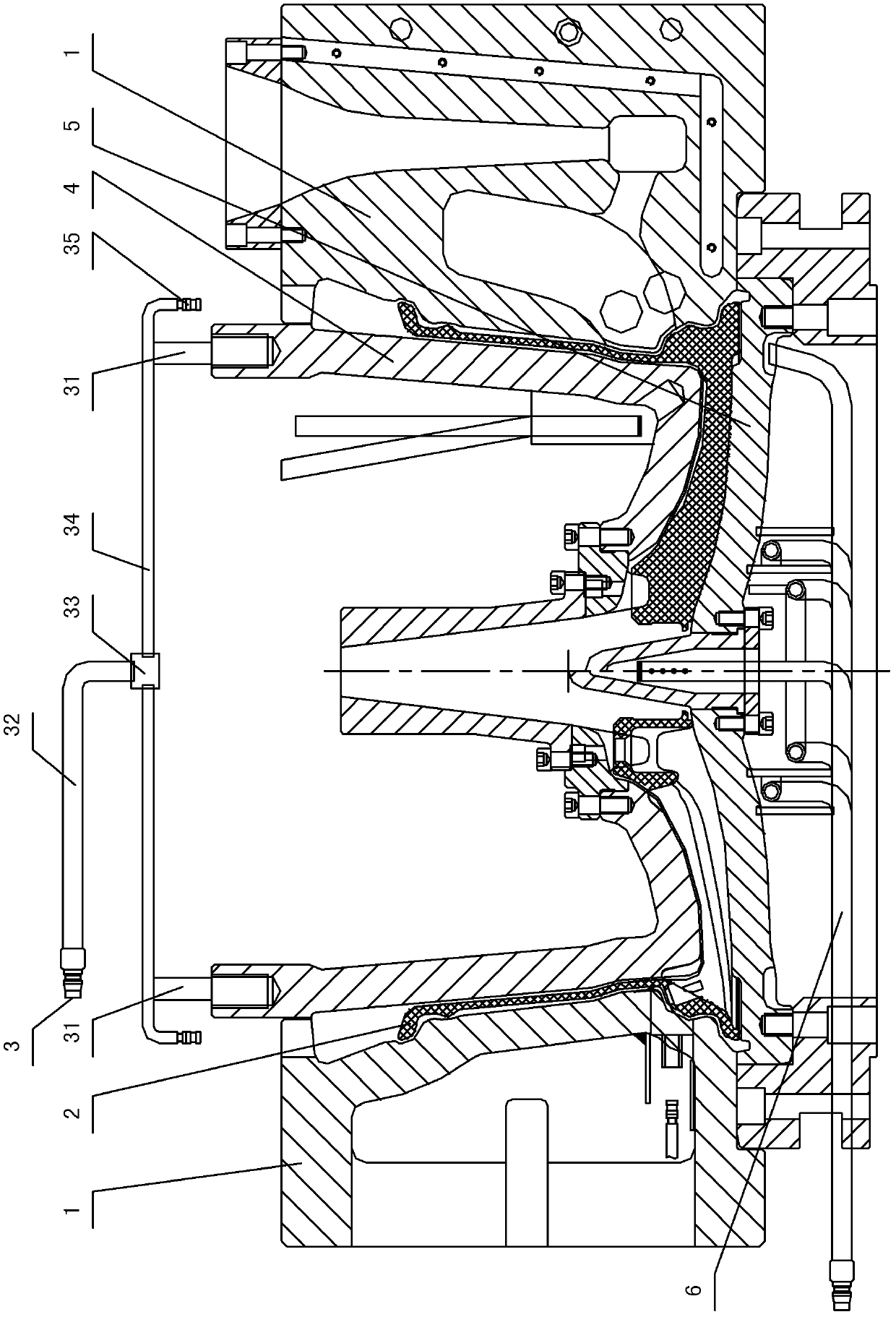
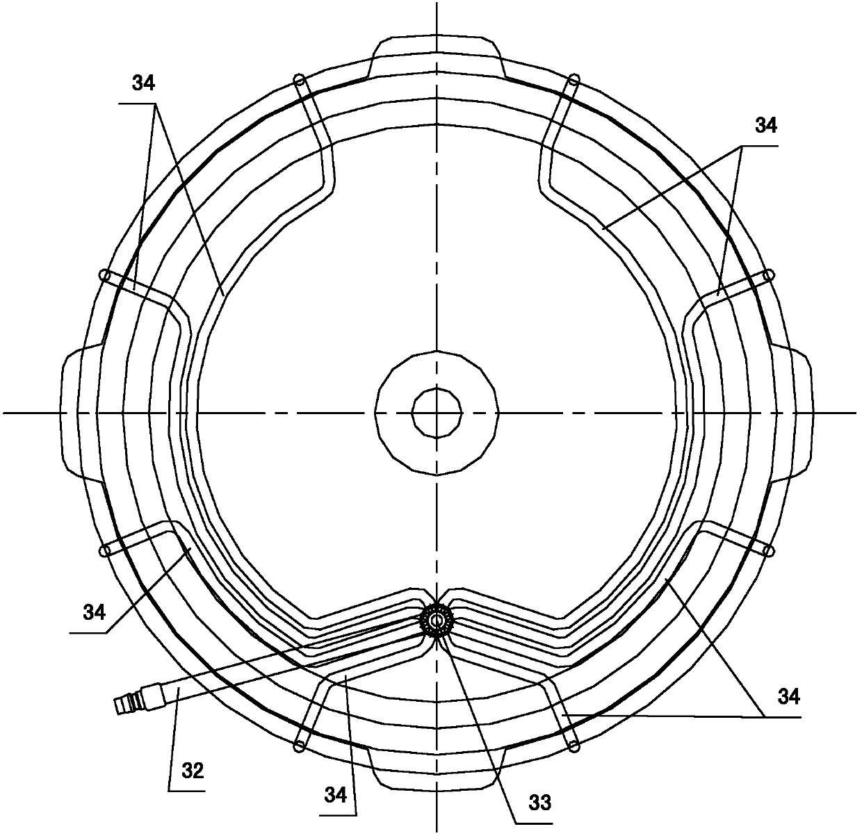
[0022] Depend on figure 1 with figure 2 The shown structural representation of the casting method of the wheel hub of the present invention and the water mist cooling device used therein shows that the casting method of the wheel hub comprises the following steps:

[0023] 1) The mold of the wheel hub is composed of upper mold 4, lower mold 5 and side mold 1. After installing the water cooling device 6 under the lower mold 5, fix the lower mold 5 on the casting machine, and then install the side mold 1 and upper mold 4. Then a water mist cooling device 3 is installed on the top of the upper mold 4;

[0024] 2) After installing the mold on the casting machine, pour liquid aluminum water into the cavity of the mold for filling;

[0025] 3) After the casting is completed, the water cooling device 6 is used for cooling. When the hub c...


PUM


Abstract

The invention discloses a casting method for a hub, which comprises the following steps of: 1) arranging a mold and a cooling device on a casting machine; 2) casting liquid aluminum water into a cavity of the mold; 3) performing primary cooling by using a water cooling device (6), and opening a side mold (1); 4) starting a water mist cooling device (3), and ensuring that the water mist cooling device (3) is directly aligned with the edge part of a hub casting (2) and performs water mist cooling; 5) cooling to room temperature, and stripping; 6) demolding. In the water mist cooling device usedin the casting method, one end of a mist pipe is communicated with a mist source, the other end of the mist pipe is communicated with a mist spray head (35), the mist pipe is fixed on the top of an upper mold (4) through a connecting bracket (31), and the mist spray head (35) is positioned above the edge part of the hub casting (2). Therefore, casting defects such as shrinkage and the like on theedge of the upper end of the hub are overcome; in addition, an ellipse is difficult to form after a rim at the uppermost end of the casting is demolded.

Description

technical field [0001] The invention relates to the field of matching equipment for casting machines, in particular to a casting method for wheel hubs. Background technique [0002] At present, most wheels are made of aluminum alloy wheels. There are three manufacturing methods: gravity casting, forging and low-pressure precision casting. Among them, gravity casting is to use gravity to pour aluminum alloy solution into the mold. After forming, it can be finished by lathe treatment and grinding. Production. Because of its simple manufacturing process, no precision casting process, low cost and high production efficiency, it is adopted by most manufacturers. But, there is following shortcoming in the casting method of this wheel hub: [0003] 1) During the production process, the hub casting in the mold is placed horizontally, in other words, the radial plane of the hub is placed horizontally, therefore, the hub mold is composed of an upper mold, a lower mold and a side mol...

Claims


Application Information

Patent Timeline
Patent Type & Authority Patents(China)
IPC IPC(8): B22C9/28B22D30/00
Inventor 何灿东陈木星刘建高
Owner NINGBO CANDONG MOLD TECH
Learn More