Loop pin

A ring pin and head technology, applied in the field of high-strength ring pins, can solve problems such as the inability to obtain specified strength, and achieve the effects of a good environment, improved production efficiency, and reduced manufacturing costs

Inactive Publication Date: 2012-04-18
M I T INT
View PDF7 Cites 1 Cited by
  • Summary
  • Abstract
  • Description
  • Claims
  • Application Information

AI Technical Summary

Problems solved by technology

[0006] However, when the pitch is dense, there is a problem that the prescribed strength cannot be obtained anyway

Method used


Image

  • Loop pin
  • Loop pin
  • Loop pin

Examples


Embodiment

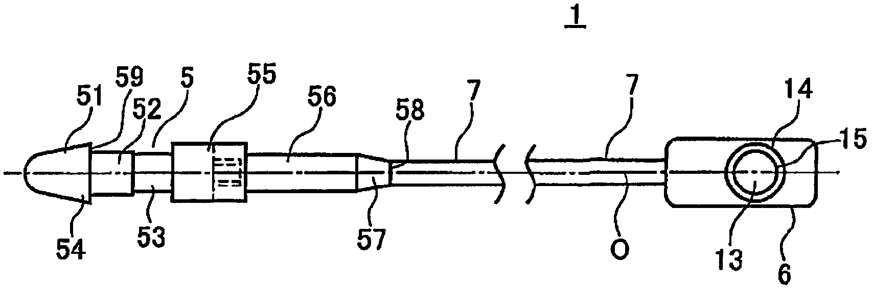
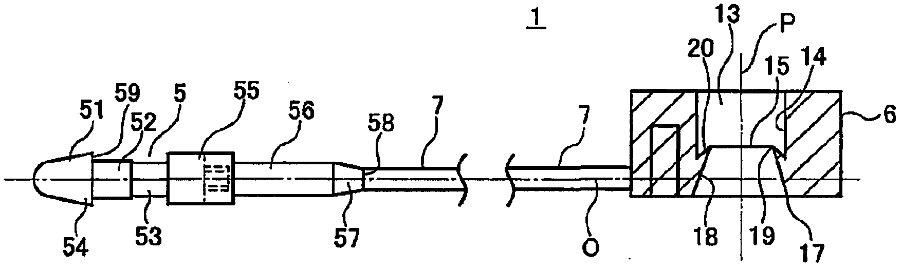
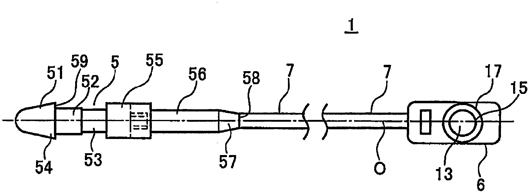
[0051] Next, specific examples of the ring pin 1 of the present invention will be described. That is, using commercially available polypropylene resin integral molding processing has Figures 1 to 4 Ring pins of the construction shown. The length of the head portion 51 of the insertion head portion 5 is 2 mm, and the length of the maximum diameter portion of the lower end portion 54 of the head portion 51 is 1.76 (preferably 1.75-1.85 mm); The length of 52 is 1.3mm (preferably 1.20-1.35mm), and its diameter is 1.29mm (preferably 1.20-1.35mm); meanwhile, the length of the second narrow portion 53 is 1.0mm (preferably 0.8-1.3mm) ) with a diameter of 1.18 mm (preferably 1.15 to 1.25 mm). In addition, the thickness of the fiber portion is 1.17 mm (preferably 0.70 to 1.18 mm).

[0052] Also, in the figure, 55 is an enlarged diameter portion connected to the end of the second narrow diameter portion 53 ; 56 is an unextended portion connected to the enlarged diameter portion 55 an...


PUM


Abstract

Disclosed is a loop pin that uses a polypropylene-based synthetic resin, is environmentally friendly, and allows decreased manufacturing costs and increased production efficiency. A loop pin (1) is constituted such that an insertion head section (5) comprises a first thin section (52) having a diameter smaller than the greatest diameter of a head section (51), and a second thin section (53) having a diameter smaller than that of the first thin section (52); the through hole (13) of a socket section (6) is provided with an annular step section (15). The step section (15) comprises a first inclined section (18) and a second inclined section (20) that are formed contiguously at prescribed angles.

Description

technical field [0001] The present invention relates to a ring pin, which can bind clothes, socks, etc. into a bundle, or insert one end of it into a product to install labels such as brand labels, price tags, raw material instructions, and instruction manuals. Specifically, the present invention The present invention relates to a ring pin capable of increasing the strength when the above-mentioned label or the like is attached to the above-mentioned product. Background technique [0002] Generally, the ring pin 1 is composed of a fiber part 7 that penetrates a label or the like to form a ring, an insertion head 5 that is arranged at one end of the fiber part 7, and a socket part 6 that is arranged at the other end of the fiber part 7, etc., and the socket part 6 has an insertion hole 13 for inserting the insertion head 5 . [0003] and, if Figure 10 , 11 As shown, when an appropriate driving device (gun) is used, a plurality of ring pins 1 are temporarily fixed on the tw...

Claims


Application Information

Patent Timeline
Patent Type & Authority Applications(China)
IPC IPC(8): B65D63/12B65C7/00G09F3/16
CPCG09F3/14B65D63/1081G09F3/16G09F3/037
Inventor 上野英幸藤原一司
Owner M I T INT
Why Eureka
Try Eureka