
Method for encapsulating chips and support plates

A packaging method and chip technology, which is applied in the manufacture of electrical components, electrical solid devices, semiconductor/solid devices, etc., can solve the problems of uncompetitiveness, cost increase, and expensive packaging molding materials, so as to avoid bending, Effects of saving cost and reducing total thickness

Inactive Publication Date: 2014-03-26
KINSUS INTERCONNECT TECH
View PDF4 Cites 0 Cited by
  • Summary
  • Abstract
  • Description
  • Claims
  • Application Information

AI Technical Summary

Problems solved by technology

[0006] In addition, the thickness of the packaging structure of the chip and the substrate is 1.2mm-2.0mm, which is obviously insufficient in the design of light, thin and small electronic products, and the price of the plastic packaging molding material used for plastic packaging (Molding) Expensive, which also makes the cost higher and not competitive in the market

Method used


Image

  • Method for encapsulating chips and support plates
  • Method for encapsulating chips and support plates
  • Method for encapsulating chips and support plates

Examples


Embodiment Construction

[0047] The implementation of the invention will be described in more detail below in conjunction with the drawings and component symbols, so that those skilled in the art can implement it after studying this specification.

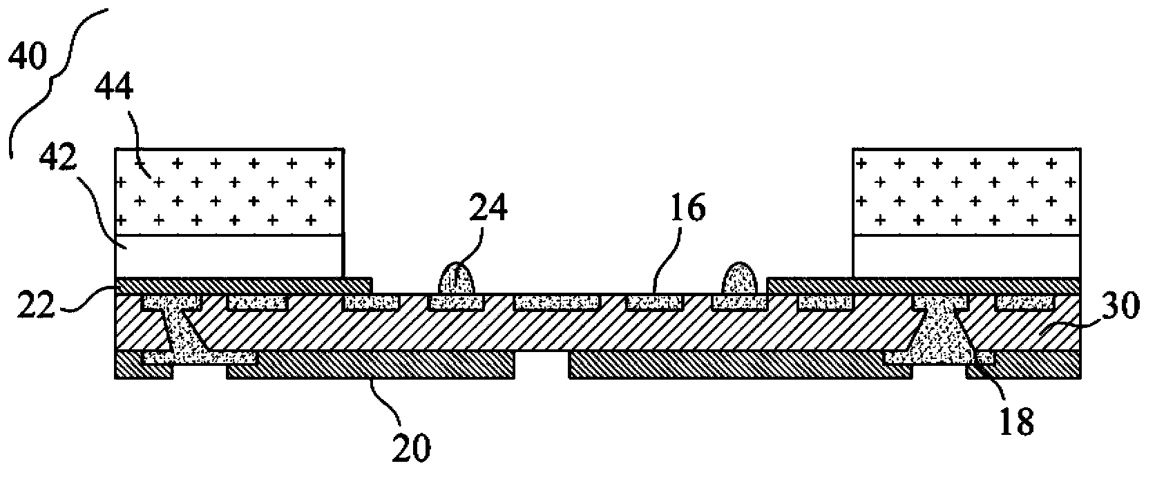
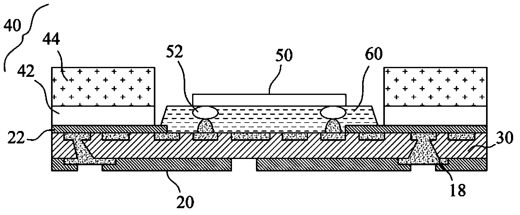
[0048] see figure 2 , is a flow chart of the chip and carrier board packaging method of the present invention. The chip and carrier packaging method S1 of the present invention includes a thin chip carrier manufacturing step S10, a structural layer manufacturing step S20, a chip connection step S30, and an injection material filling step S40. Thin chip carrier production step S10 includes substrate preparation step S11, partial etching step S13, image transfer step S15, layer build-up step S17, and carrier removal and etching step S19, the detailed method will be coordinated with Figure 3A to Figure 3K to explain step by step.

[0049] like Figure 3A As shown, the substrate preparation step S11 is to prepare a carrier 100 with a copper layer 10, the ...


PUM


Abstract

The invention provides a method for encapsulating chips and support plates. The method comprises the following steps: producing thin-type chip support plates with the total thickness ranging from 70 Mum to 150 Mum, wherein each thin-type chip support plate comprises a dielectric material layer, circuit metal layers stacked and connected by the dielectric material layer and a welding pad 10 Mum-15 Mum protruding out of the dielectric material layer; producing a structural layer, wherein stable structures are arranged at the periphery of the thin-type chip support plate; connecting a chip, wherein the chip is arranged in an accommodating space, and the pin of the chip is connected with a welding pad; filling an injection material, wherein the accommodating space below the chip is filled with the injection material, and the total thickness after encapsulation ranges from 300 Mum to 850 Mum. The total encapsulation thickness and cost are lowered as cementing encapsulation is not needed, and the stable structure can prevent the thin-type chip support plates from bending.

Description

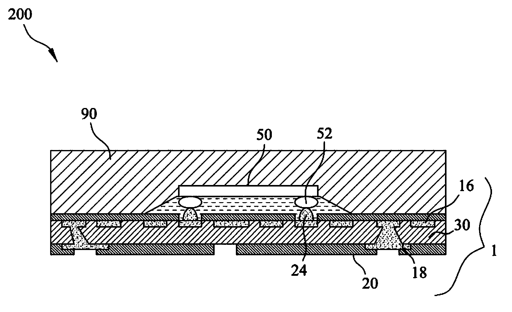
technical field [0001] The invention relates to a packaging method of a chip and a carrier board, in particular, a stable structure is made on a thin carrier board to hold the chip. Background technique [0002] see figure 1 , is a schematic cross-sectional view of a package structure of a chip and a substrate in the prior art. like figure 1 As shown, the packaging structure 200 of the prior art chip and carrier includes a thin chip carrier 1, a chip 50 and Injecting the material 60 and the adhesive molding material 90 . [0003] The first circuit metal layer 16 is embedded in the dielectric material layer 30 and forms a coplanar plane with the dielectric material layer 30 , and the second circuit metal layer 18 fills the other surface formed on the dielectric material layer 30 , and fill the holes in the dielectric material layer 30 to connect with the first circuit metal layer 16 . The thin chip carrier 1 further includes a plurality of pads 24 protruding from the cop...

Claims


Application Information

Patent Timeline
Patent Type & Authority Applications(China)
IPC IPC(8): H01L21/56H01L21/60H01L21/64
CPCH01L2224/73204H01L2224/16225H01L2224/32225H01L2924/00H01L21/4846H01L21/54H01L24/81
Inventor 林定皓吕育德卢德豪
Owner KINSUS INTERCONNECT TECH
Learn More