
Vertical mist eliminator

A fog eliminator and vertical technology, which is applied in the field of exhaust gas purification and treatment devices, can solve the problems that condensed water cannot be discharged quickly and the effect of fog elimination is not ideal.

Active Publication Date: 2012-04-25
ANHUI SAFE ELECTRONICS
View PDF8 Cites 7 Cited by
  • Summary
  • Abstract
  • Description
  • Claims
  • Application Information

AI Technical Summary

Problems solved by technology

The condensed water of this kind of anti-fog device cannot be discharged quickly, so the anti-fog effect is not ideal enough

Method used


Image

  • Vertical mist eliminator
  • Vertical mist eliminator
  • Vertical mist eliminator

Examples


Embodiment Construction

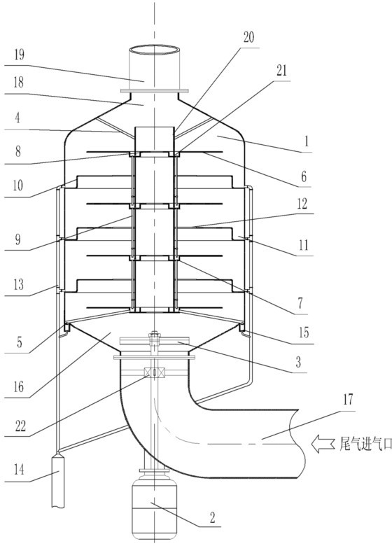
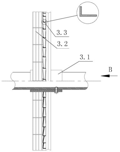
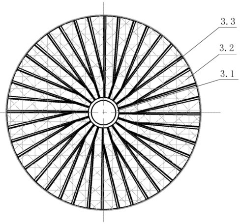
[0018] like figure 1 As shown, the present invention is a vertical mist eliminator, which includes a vertical cylinder 1, the air inlet 16 at the lower end of the cylinder 1 is connected to the air inlet pipe 17, and the exhaust port 18 at the upper end of the cylinder 1 is connected to the The exhaust pipe 19 is connected to each other. At the bottom of the bend of the air intake pipe 17, an anti-mist motor 2 is installed. A fixed seat bearing 22 is installed inside, and the output shaft of the anti-fog motor 2 is inserted into the inner hole of the fixed seat bearing 22, thereby preventing the output shaft from shaking when rotating at high speed. On the output shaft of the fog-eliminating motor 2, a fog-eliminating fan blade 3 is installed, and the fog-eliminating fan blade 3 is located at the air inlet 16 of the cylinder body 1 . Use the induced draft fan to inhale the water mist and the gas purified by the water mist from the air intake pipe 17, and after being blocked ...


PUM


Abstract

The invention relates to a vertical mist eliminator. The vertical mist eliminator comprises a vertically-arranged cylinder, wherein the vertically-arranged cylinder is connected with a gas entering pipeline and a gas exhaust pipeline. A mist eliminating motor is arranged on the bending position of the gas entering pipeline. A mist eliminating fan blade is arranged on an output shaft of the mist eliminating motor. An outer drainage pipe is arranged on the outer side of the cylinder. A plurality of inner damping plates and a plurality of outer damping plates are arranged inside the cylinder, wherein the inner damping plates and the outer damping plates are intervally arranged. The inner damping plates are provided with circular inner backwater tanks, wherein the circular inner backwater tanks recess downward. Outer backwater tanks are arranged between the side edges of the outer damping plates and the inner wall of the cylinder, wherein the outer backwater tanks recess downward. With the present invention, the induced draft fan is adopted to absorb the water mist and the tail gas purified by the water mist from the gas entering pipeline; with the mist eliminating fan blade, the water mist hits the high speed centrifugation shunt blades and is coagulated into the water; the water and the gas are subjected to rechanneling and multiple friction rolling on the positions tightly close to the inner wall of the cylinder, and then hit the inner damping plates, the outer damping plates and the inner wall of the cylinder, the water is discharged by the drainage pipe after coagulating, and the gas is discharged by the gas exhaust pipeline. According to the vertical mist eliminator, the mist eliminating effect is significant, and the flow rate of the air flow is not affected.

Description

technical field [0001] The invention relates to a tail gas purification treatment device, in particular to a device for eliminating water mist in an atomization dust removal device. Background technique [0002] With the development of industry, the discharge of various industrial waste gases is increasing day by day. Industrial waste gases often contain smoke and a large amount of toxic substances, which will not only pollute the environment, but also seriously affect the health of workers and residents around the factory. Existing exhaust gas treatment devices mainly spray water mist on the exhaust gas to mix the smoke and toxic substances in the exhaust gas into the water mist, but there is no good way to completely separate the water mist from the air flow, so the discharged Soot and toxic substances in the exhaust gas still cannot be effectively removed. At present, there are also methods such as wind blocking to condense and separate the water mist, but once the w...

Claims


Application Information

Patent Timeline
Patent Type & Authority Applications(China)
IPC IPC(8): B01D45/14
Inventor 张宏生
Owner ANHUI SAFE ELECTRONICS
Learn More