

Foaming device
A foamer and gas nozzle technology, applied in the direction of injection device, liquid injection device, etc., can solve the problems of poor effect of medicament or foaming agent, large foam diameter, unsatisfactory foam mineralization effect, etc., and achieve optimal foam mineralization. effect, avoid clogging and corrosion
- Summary
- Abstract
- Description
- Claims
- Application Information
AI Technical Summary
Problems solved by technology
Method used
Image

Examples
Embodiment Construction
[0017] The present invention will be further described in detail below in conjunction with the accompanying drawings and specific embodiments.
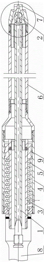
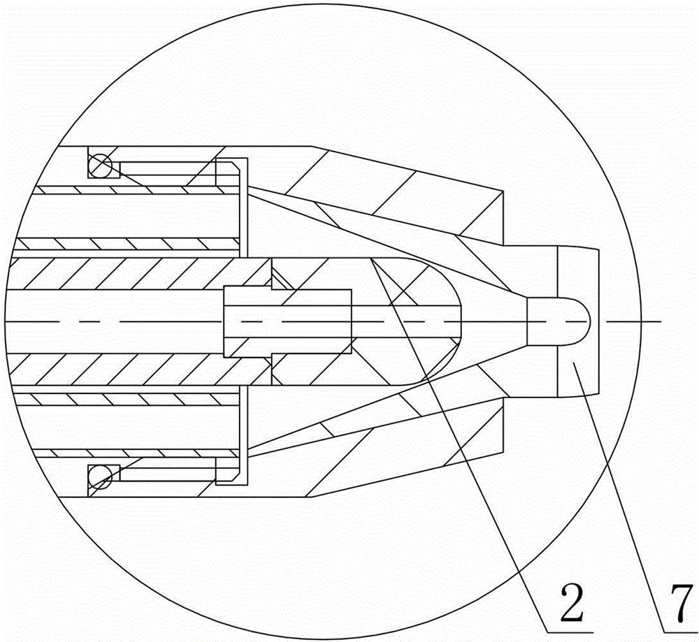
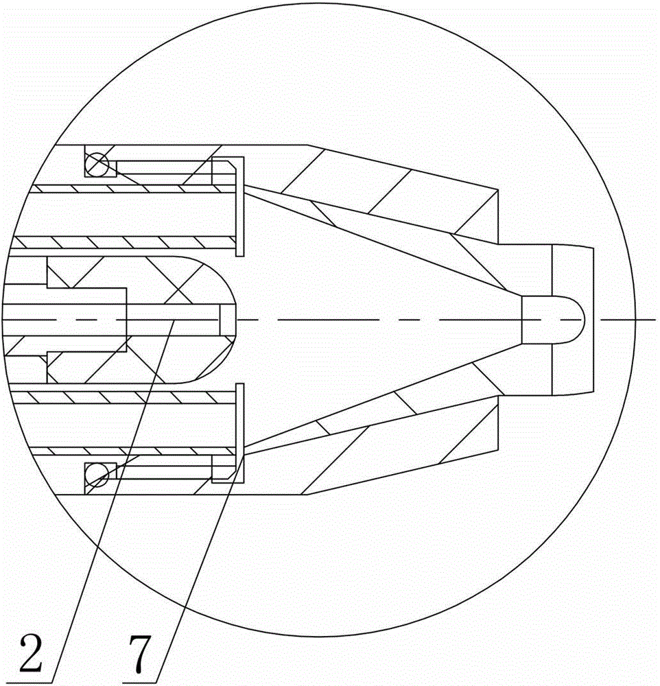
[0018] Such as figure 1 , figure 2 with image 3 As shown, the foamer of the present invention includes a liquid nozzle assembly and a gas nozzle assembly, the liquid nozzle assembly includes a liquid inlet pipe 1 and a liquid nozzle 2 positioned at the tail of the liquid inlet pipe 1, and the gas nozzle assembly includes an air inlet pipe 3 and a gas nozzle 7 , The liquid inlet pipe 1 is sleeved in the air inlet pipe 3 in a coaxial shape. The ejection direction of liquid and gas is the front, and the liquid nozzle 2 is located at the rear end of the gas nozzle 7 . The invention integrates the liquid nozzle assembly and the gas nozzle assembly, and adopts a nested design that cooperates with each other and does not interfere with each other, so that the liquid containing all kinds of medicaments and the high-pressure gas can be mi...
PUM
 Abstract
Description
Claims
Application Information