Crane and sub arm installing device thereof

A technology for installing devices and jibs, which is applied to cranes and other directions, can solve the problems of difficult alignment, time-consuming and labor-intensive problems, and achieve the effects of small structural changes, improved operability, and simple and practical structure

Active Publication Date: 2012-04-25
SANY AUTOMOBILE HOISTING MACHINERY
View PDF5 Cites 15 Cited by
  • Summary
  • Abstract
  • Description
  • Claims
  • Application Information

AI Technical Summary

Problems solved by technology

[0011] In order to overcome the above-mentioned defects and deficiencies of the prior art, the object of the present invention is to provide a jib installation device, which can realize the automation of jib installation, and avoid the defects of time-consuming, labor-intensive and difficult alignment caused by manual work. Reduce the requirements on the working environment, and can realize the control of moving speed

Method used


Image

  • Crane and sub arm installing device thereof
  • Crane and sub arm installing device thereof
  • Crane and sub arm installing device thereof

Examples


Embodiment Construction

[0035] The following will clearly and completely describe the technical solutions in the embodiments of the present invention with reference to the accompanying drawings in the embodiments of the present invention. Obviously, the described embodiments are only some, not all, embodiments of the present invention. Based on the embodiments of the present invention, all other embodiments obtained by persons of ordinary skill in the art without creative efforts fall within the protection scope of the present invention.

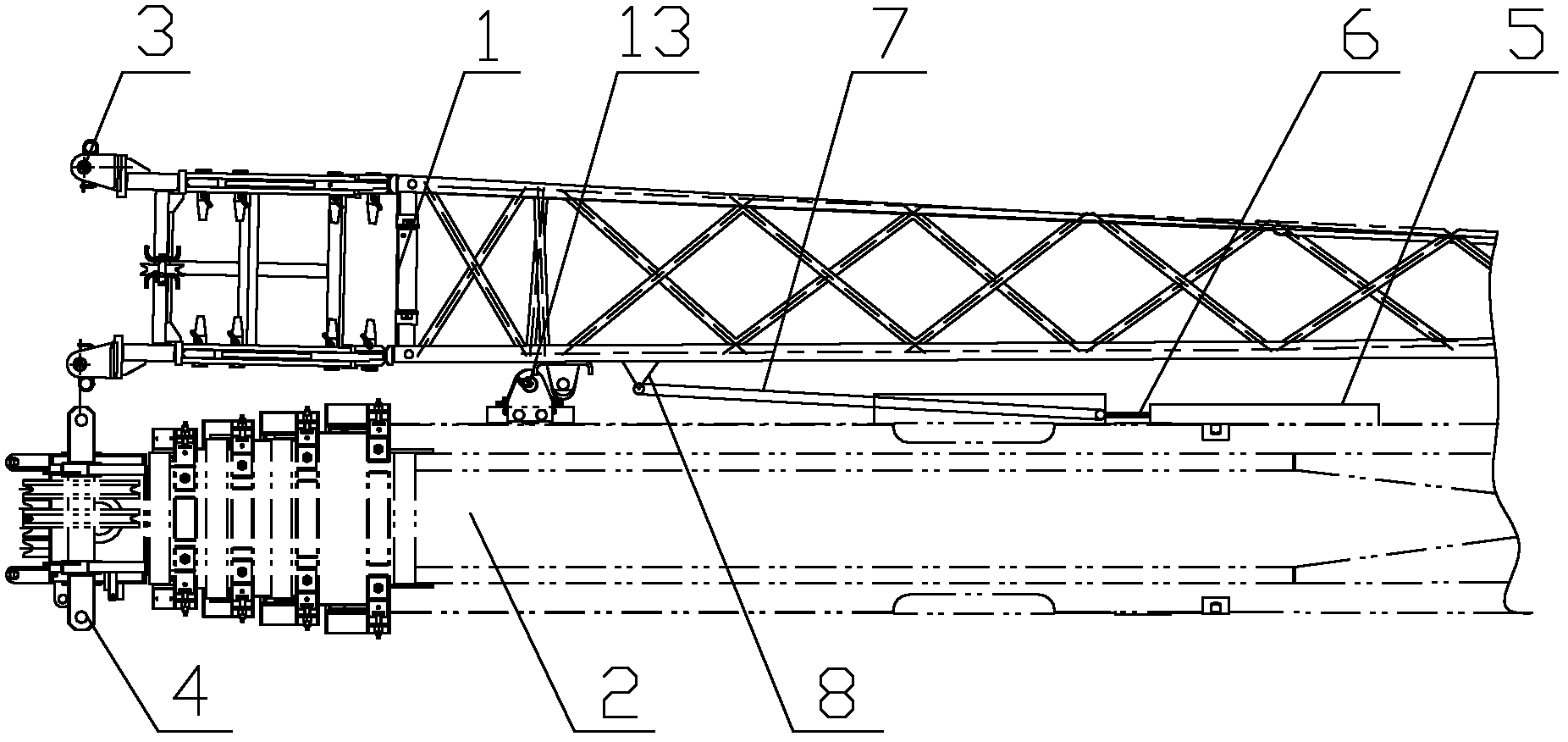
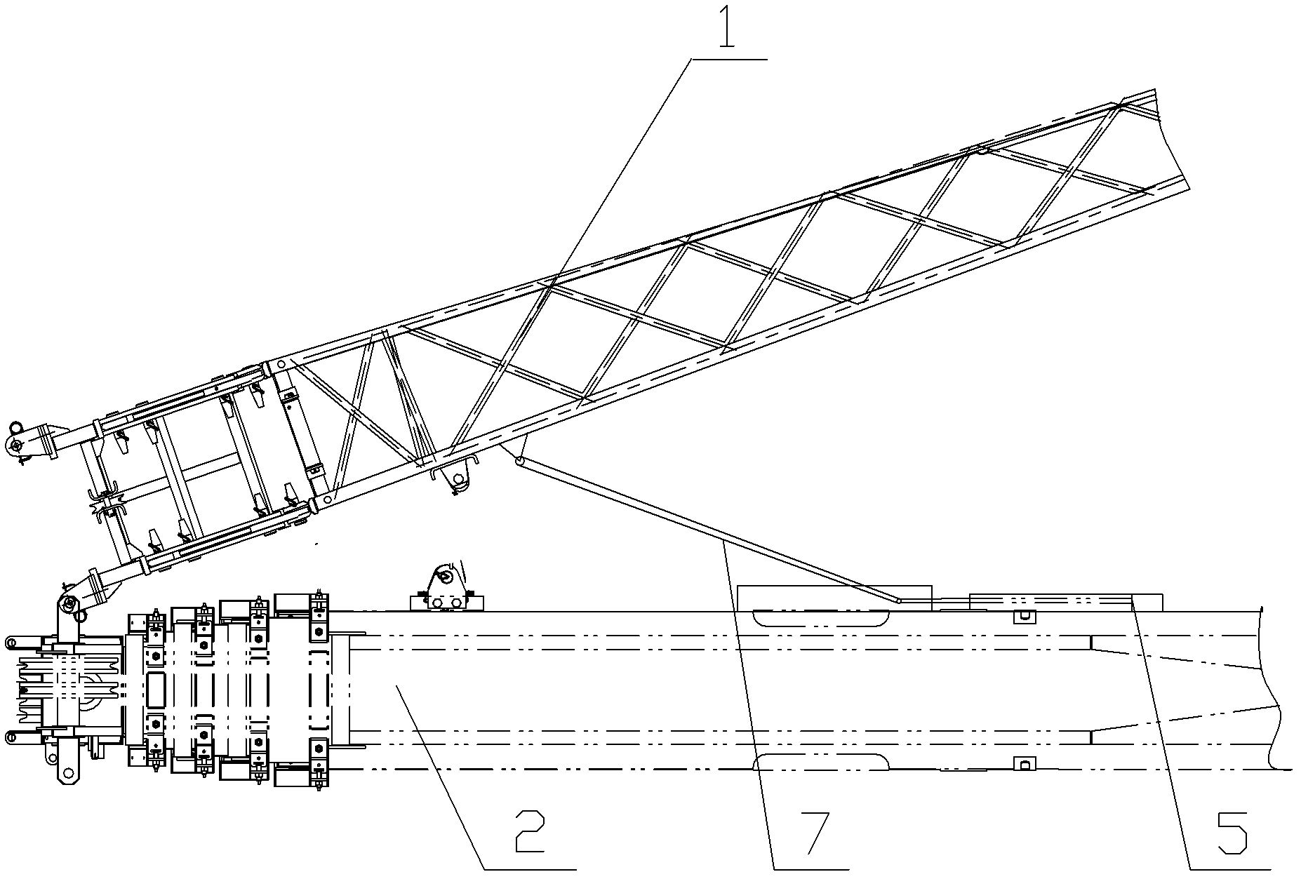
[0036] figure 1 It is a structural diagram of a jib installation device according to an embodiment of the present invention. Such as figure 1 As shown, the auxiliary arm installation device of the present invention is used to dock the first installation part 3 and the second installation part 4, wherein the first installation part 3 is located at the tail of the auxiliary arm 1, and the second installation part 4 is located at the head of the main arm 2 departmen...


PUM


Abstract

The invention provides a crane and a sub arm installing device thereof. The device comprises a linear driving mechanism and a connecting rod, wherein the linear driving mechanism comprises a fixed component and a movable component, the movable component is fixedly arranged on the side surface of a main arm and does linear reciprocating movement relative to the fixed component, the reciprocating movement direction is parallel to the side surface of the main arm, the first end of the connecting rod is hinged onto a hinging seat of a sub arm, the movable component pushes and pulls the second end of the connecting rod, and further, the first end of the connecting rod drives the sub arm to swing around the main arm. The crane and the sub arm installing device can realize the high-automation installation and folding of the sub arm and have the advantages that the operation efficiency is high, the alignment is precise, the applicability is high, the swinging speed is controllable, and the like.

Description

technical field [0001] The invention relates to the field of engineering machinery, in particular to a crane jib installation device and a crane including the jib installation device. Background technique [0002] The jib system of current cranes (especially truck cranes) often includes a main jib (hereinafter referred to as the main jib) and an auxiliary jib (hereinafter referred to as the jib). The setting of the auxiliary arm can compensate the operating height of the main arm and expand the operating range of the main arm. [0003] The assembly connection of the auxiliary arm and the main arm is usually formed by hinged connection of four forks at the tail of the auxiliary arm and four joint holes at the head of the main arm. When the jib is not working, the jib is folded on the side or below the main arm; when the jib is required to work, the jib is deployed and installed on the boom head of the main arm. [0004] When installing the auxiliary arm, it is usually first...

Claims


Application Information

Patent Timeline
Patent Type & Authority Applications(China)
IPC IPC(8): B66C23/62B66C23/64
Inventor 钟爱平魏风波程荣国
Owner SANY AUTOMOBILE HOISTING MACHINERY
Why Eureka
Try Eureka