A Field of View Alignment Method for Line Array Imaging Optical Load in Satellite Stray Light Test

A technology of imaging optics and stray light, which is applied in the field of satellite stray light testing, can solve the problems of narrow notch of extinction equipment, difficulty in aligning the field of view of the load, and difficulty in aligning the field of view of the optical load with the notch of the extinction equipment, etc., to achieve effective Instructional significance, risk reduction effect

Active Publication Date: 2020-04-21
SHANGHAI SATELLITE ENG INST
View PDF8 Cites 0 Cited by
  • Summary
  • Abstract
  • Description
  • Claims
  • Application Information

AI Technical Summary

Problems solved by technology

[0005] In view of the defects in the prior art, in order to reduce the operational risk of satellite stray light testing and solve the problem of difficult alignment of the optical load field of view and the notch of the extinction equipment during the test, the purpose of the present invention is to provide a linear array for satellite stray light testing The field of view alignment method of the imaging optical payload solves the problem of difficult alignment of the field of view of the payload due to the narrow slot of the extinction device during the whole star stray light test, and reduces the risk of the whole star operation during the test The preparation work before the test has important guiding significance

Method used


Image

  • A Field of View Alignment Method for Line Array Imaging Optical Load in Satellite Stray Light Test
  • A Field of View Alignment Method for Line Array Imaging Optical Load in Satellite Stray Light Test

Examples


Embodiment Construction

[0032] The present invention will be described in detail below in conjunction with specific embodiments. The following examples will help those skilled in the art to further understand the present invention, but do not limit the present invention in any form. It should be noted that for those of ordinary skill in the art, several changes and improvements can be made without departing from the concept of the present invention. These all belong to the protection scope of the present invention.

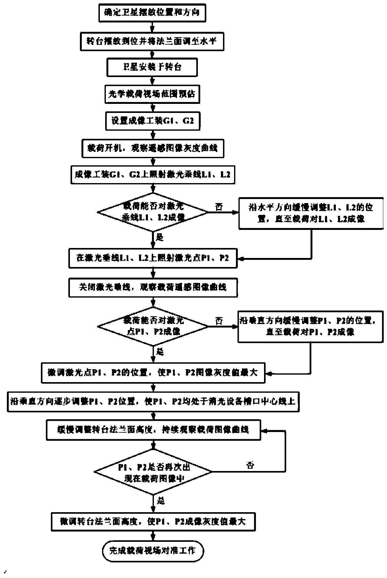
[0033] The present invention provides a field of view alignment method for linear array imaging optical load in satellite stray light test, which includes the following steps:

[0034] (1) Determine the location and direction of the satellite in the test site;

[0035] (2) Place the turntable in place on the test site and level the flange surface of the turntable;

[0036] (3) Install the satellite on the flange surface of the turntable according to the direction determined in step 1;

[0037] ...


PUM


Abstract

The invention provides the field-of-view alignment method of a linear array imaging optical load in a satellite stray light test. The method comprises the following steps of determining the locating place and the direction of a satellite in a test site; placing a rotation table in place and leveling; installing the satellite in the rotation table; pre-estimating a load field-of-view range and setting imaging tools G1 and G2; on the imaging tools G1 and G2, through a laser level meter and a laser, irradiating a laser vertical line and a laser point, and determining a load field-of-view horizontal plane; and adjusting a rotation table flange surface height so that a load field-of-view surface is superposed with the center plane of an extinction device notch and the alignment work of a load field of view is completed. In the invention, the alignment method of the linear array imaging optical load field of view and the extinction device notch during the satellite stray light test is provided; a problem that load field of view alignment is difficult due to the narrow extinction device notch during a whole star stray light test is solved; the risk of whole star operation during the testis reduced; and a practical guidance meaning is possessed for satellite stray light test preparation work.

Description

Technical field [0001] The invention relates to the technical field of satellite stray light testing, in particular to a field of view alignment method for linear array imaging optical loads in satellite stray light testing. Background technique [0002] The satellite stray light test is to simulate the image of dark targets in the field of view through the optical load under simulated on-orbit lighting conditions, and analyze the stray light suppression effect of the optical load. Compared with the more mature stray light test methods for optical systems, the stray light test under the condition of the whole star is closer to the actual illumination situation in orbit, and the whole star stray light test can also realize the stray light of the star. Inhibition measures are verified. However, the stray light test of the whole star is still in the exploratory stage due to the limitation of test equipment, test environment and test risk. [0003] In the satellite stray light test, ...

Claims


Application Information

Patent Timeline
Patent Type & Authority Patents(China)
IPC IPC(8): G01M11/00G01S19/20G01S19/02
CPCG01M11/00G01S19/02G01S19/20
Inventor 杨春燕汪少林崔伟马文佳余辉杨珺赵其昌
Owner SHANGHAI SATELLITE ENG INST
Why Eureka
Try Eureka