Convection/radiation integrated heat exchange terminal

A technology of heat exchanger and terminal equipment, applied in the field of terminal equipment of chiller air-conditioning units, can solve the problems of easy condensation, insufficient cooling capacity, huge initial investment, etc.

Active Publication Date: 2012-04-25
膜纳柯工业科技(苏州)有限公司
View PDF6 Cites 16 Cited by
  • Summary
  • Abstract
  • Description
  • Claims
  • Application Information

AI Technical Summary

Problems solved by technology

When the traditional single radiant terminal is used, it often has the disadvantages of insufficient cooling capacity and easy condensation. It often needs to be equipped with an independent fresh air system, so the initial investment of the system will be huge.
The traditional convective heat transfer method does not have the energy-saving effect and comfort of the radiation heat transfer method during use

Method used


Image

  • Convection/radiation integrated heat exchange terminal
  • Convection/radiation integrated heat exchange terminal
  • Convection/radiation integrated heat exchange terminal

Examples


Embodiment Construction

[0021] The content of the present invention will be described in detail below in conjunction with the drawings and specific embodiments. It should be understood that the present invention is not limited to the following preferred embodiments, which are only used as illustrations of the present invention.

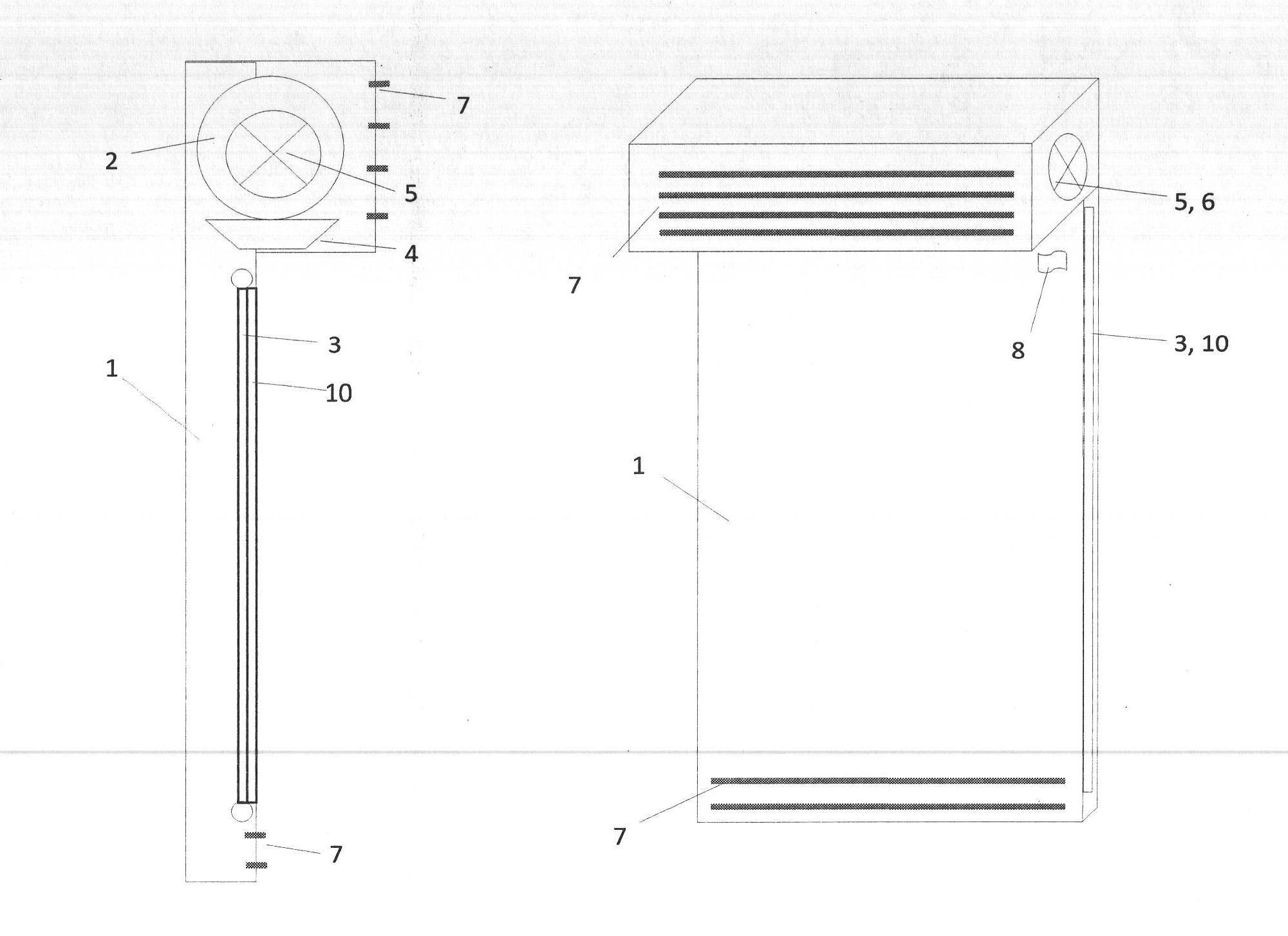
[0022] Such as figure 1. As shown, the present invention is mainly composed of a casing 1 , a first heat exchanger 2 , a second heat exchanger 3 , a condensation pan 4 , a dew point detector 8 and an electric tee 9 . The upper end inside the housing is the first heat exchanger, with a built-in fan 5 to enhance convection, round holes at both ends of the housing are air inlets 6, and louver air outlets 7 are opened on the protruding surface of the upper part of the housing.

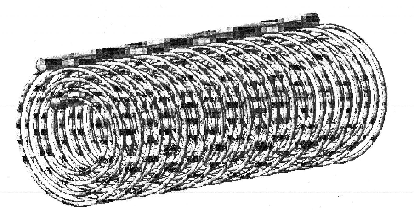
[0023] Such as figure 2. As shown, the first heat exchanger 2 of the present invention, namely the convective heat exchanger, is a coiled capillary heat exchanger.

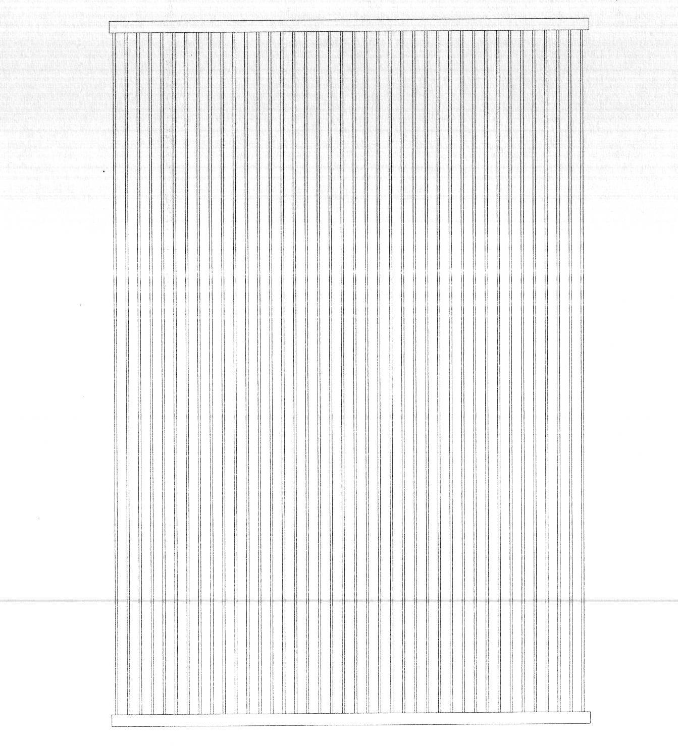
[0024] Such as image 3. As show...


PUM


Abstract

The invention relates to convection / radiation integrated air conditioner heat exchange terminal equipment. A tubular capillary pipe heat exchanger is arranged at the upper part of the equipment and used as a first heat exchanger 2, and the first heat exchanger is provided with a condensate pan 4, a fan 5, an air inlet 6 and an air outlet 7, so that the first heat exchanger realizes convective heat exchange with a room and has a dehumidifying function; and a sheet like capillary pipe heat exchanger is arranged at the lower part of the equipment and used as a second heat exchanger 3, the second heat exchanger is connected with the first heat exchanger in series through a pipeline, a phase change energy storage material is arranged between the second heat exchanger and a shell, and the second heat exchanger is provided with a humiture sensor 8 and an electric three-way valve 9, so that the second heat exchanger realizes radiation heat exchange with the room and has high comfort property and energy saving property. The equipment integrates a convective heat exchange mode and a radiation heat exchange mode, utilizes the capillary pipes as the terminal heat exchange equipment, realizes cascading use of high temperature cold water, and meets the requirements for energy saving and comfort.

Description

technical field [0001] The present invention relates to an air conditioner terminal equipment, more specifically, relates to a chilled water air conditioner unit terminal equipment. Background technique [0002] At present, the terminal equipment of the air conditioning unit mostly adopts the soda-water type and the refrigerant type equipment. In order to achieve the purpose of regulating the indoor environment, these terminal devices often adopt the following two heat transfer methods: radiation and convection. The traditional radiation heat exchange terminal is mainly radiant ceiling; and the traditional convection method is represented by fan coil unit. When the traditional single radiant terminal is used, it often has the disadvantages of insufficient cooling capacity and easy condensation. It often needs to be equipped with an independent fresh air system, so the initial investment of the system will be huge. The traditional convective heat transfer method does not ha...

Claims


Application Information

Patent Timeline
Patent Type & Authority Applications(China)
IPC IPC(8): F24F5/00F24F13/30
Inventor 郭海新
Owner 膜纳柯工业科技(苏州)有限公司
Why Eureka
Try Eureka