Method for laying lining side support block row of rotary kiln

A technology of rotary kiln and block, applied in the direction of rotary drum furnace, lining repair, furnace, etc., to ensure the service life, save the time of installation and removal of support, and improve the effect of horizontal transportation environment

Active Publication Date: 2012-04-25
CHINA MCC17 GRP
View PDF5 Cites 10 Cited by
  • Summary
  • Abstract
  • Description
  • Claims
  • Application Information

AI Technical Summary

Problems solved by technology

[0003] The purpose of the present invention is to solve the above-mentioned shortcomings in the prior art, to provide a method for building a row of supporting blocks on the side of the rotary kiln lining, which not only effectively prevents the loosening of the refractory lining blocks, but also prevents the cement joints between the blocks from sticking together. Not a good problem, and it should be conducive to the horizontal transportation in the kiln and shorten the construction period of the masonry

Method used


Image

  • Method for laying lining side support block row of rotary kiln
  • Method for laying lining side support block row of rotary kiln

Examples


Embodiment Construction

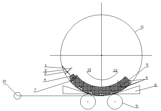
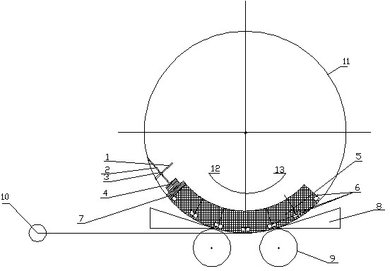
[0018] For further describing the present invention, below in conjunction with figure 1 A method for building a row of supporting blocks for the lining of a rotary kiln according to the present invention will be further described with examples.

[0019] The first step is to pop up the welding reference line.

[0020] Insert the wooden wedge (8) between the supporting surface of the rotary kiln (11) kiln body and the kiln body roller (9) to fix the rotary kiln (11) kiln body. A welding datum line parallel to the center line is elastically set on the inner wall of the kiln shell of the rotary kiln (11).

[0021] The second step is to build the first set of blocks.

[0022] Weld the anchors (6) of the first group of blocks in the first column along the welding reference line, and weld one anchor (6) between two adjacent blocks in the same ring. Build the first row of blocks (5) in the counterclockwise direction (13), and tap the anchors of the first row and the grooves of the ...


PUM


Abstract

The invention discloses a method for laying a lining side support block row of a rotary kiln; the method is characterized by comprising the following steps of: welding a first group of anchoring elements of a first row of blocks along a welding reference line, laying the first row of blocks, then welding anchoring elements of a second row of building blocks, laying the second row of building blocks, and carrying out the following steps in the same manner to finish the laying of the first group of blocks; installing side supports and plate kilns on outer side surfaces of the first row of building blocks, laying a next group of building blocks, and carrying out next steps in the same manner till closing a door; and dismantling the side supports, pouring corundum pouring layers and pointing the building blocks. Each side support comprises an upright pole, a push rod, a rotating fastener, a fine adjustment device and a wood springboard, wherein the upright poles are vertically arranged on a kiln shell in a full-length welding manner and are parallel to the building block rows; and one ends of the upright poles are welded on the kiln shell each six meters. The push rod is connected with the upright pole through the rotating fastener; one end of the push rod is connected with the fine adjustment device; the wood springboard is arranged on the side surface of the building block, and the fine adjustment device is adjusted so that the push rods are propped against the building block rows through the wood springboard. According to the method, the building block looseness and the possibility that the kiln shell becomes red after being put into production are avoided, the service life of the rotary kiln is ensured, and the laying construction period is shortened.

Description

technical field [0001] The invention relates to a method for building the inner lining of a rotary kiln, in particular to a method for building the side support block columns of the inner lining of the rotary kiln, which is applied to the refractory block inner lining of the rotary kiln with high temperature, high pressure and large wear in the pellet and cement production lines Field of masonry construction. Background technique [0002] The masonry of the refractory block lining of the rotary kiln of the existing pellet and cement production line is to install radial steel pipes and fine-tuning combined support inside the rotary kiln, and tighten the refractory lining of the rotary kiln through two-way fine-tuning, so that the rotary kiln is refractory Lining does not come loose. Due to the staggered radial supports, the horizontal transportation in the rotary kiln is restricted, and it takes a long time to install and dismantle, which affects the construction period. At...

Claims


Application Information

Patent Timeline
Patent Type & Authority Applications(China)
IPC IPC(8): F27B7/28F27D1/16
Inventor 赵家贵刘守城
Owner CHINA MCC17 GRP
Why Eureka
Try Eureka