
Reflection-type Sagnac interference fiber current sensor

A current sensor, fiber optic current technology, applied in the direction of voltage/current isolation, etc., can solve the problems of high cost, high technical difficulty, and the polarization-maintaining delay line does not have the function of sensing, and achieves the effect of reducing technical difficulty and system cost.

Inactive Publication Date: 2012-04-25
SHANGHAI UNIV
View PDF8 Cites 18 Cited by
  • Summary
  • Abstract
  • Description
  • Claims
  • Application Information

AI Technical Summary

Problems solved by technology

Due to the extremely fast speed of light, this modulation method requires a long fiber delay line and a high modulation frequency, which is technically difficult and expensive
In addition, the polarization maintaining fiber delay line is used as a part of the sensing fiber in the fiber optic gyroscope, which can improve the sensitivity of the gyroscope, but in the fiber optic current sensor, the polarization maintaining delay line does not have the function of sensing

Method used


Image

  • Reflection-type Sagnac interference fiber current sensor
  • Reflection-type Sagnac interference fiber current sensor
  • Reflection-type Sagnac interference fiber current sensor

Examples


Embodiment 1

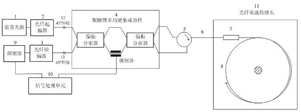
[0025] Embodiment one: see figure 1. This reflective Sagnac interference fiber optic current sensor is an active modulation type, including broadband light source 1, fiber optic polarizer 2, fiber optic analyzer 3, lithium niobate multifunctional device 4, fiber optic circulator 5, protection Bias transmission optical cable 6 , optical fiber current sensing head 11 , photodetector 9 and signal processing unit 10 . The working principle is: the light wave is output from the broadband light source 1, and becomes linearly polarized light after passing through the optical fiber polarizer 2, and the other end of the optical fiber polarizer 2 is welded with the input polarization-maintaining fiber of the lithium niobate multifunctional device 4 at 45° The input linearly polarized light is split into two orthogonal linearly polarized lights. The two polarized lights respectively enter the two arms of the Mach-Zehnder modulator after passing through the first polarization beam sp...

Embodiment 2

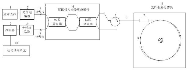
[0026] Embodiment two: see figure 2 . This reflective Sagnac interference fiber optic current sensor is a passive bias type, including broadband light source 1, fiber optic polarizer 2, fiber optic analyzer 3, lithium niobate multifunctional device 4, fiber optic circulator 5, Polarization maintaining transmission optical cable 6 , optical fiber current sensing head 11 , photodetector 9 and signal processing unit 10 . After the broadband light source 1 passes through the optical fiber polarizer 2, it is connected to an input polarization-maintaining optical fiber of the lithium niobate multifunctional integrated device 4, and another input polarization-maintaining optical fiber of the lithium niobate multifunctional integrated device 4 is connected to the optical fiber analyzer 3 , the other end of the optical fiber analyzer 3 is connected to the photodetector 9; the two output polarization-maintaining optical fibers of the lithium niobate multifunctional integrated device...


PUM


Abstract

The invention discloses a reflection-type Sagnac interference fiber current sensor. The sensor comprises: a broadband light source, a fiber polarizer, a fiber polarization analyzer, a lithium niobate multifunctional integration device, a fiber loop device, a polarization-maintaining transmission cable, a quarter wave plate, a sensing fiber, a photoelectric detector and a signal processing unit. The lithium niobate multifunctional integration device, which is formed by two polarization beam splitters, is a Mach-Zehnder phase adjusting system. The structure can realize passive bias and can realize active modulation. By using the sensor of the invention, technical difficulty of an active modulation scheme of the interference fiber current sensor can be substantially reduced. Simultaneously, unification of an optical path structure of the two schemes: the passive bias of the fiber current sensor and the active modulation can be realized.

Description

technical field [0001] The invention relates to a novel optical fiber current sensor, in particular, a reflective Sagnac interference optical fiber current sensor based on a Mach-Zehnder phase adjustment system. Background technique [0002] The current sensor is an important device for electric energy measurement and relay protection in the power system. With the development of the electric power industry, the voltage operation level is getting higher and higher, and the traditional electromagnetic current transformer has encountered great difficulties in insulation. The current transformer made of optical fiber has natural advantages in insulation, and also has the advantages of anti-electromagnetic interference, wide measurement frequency range, and digital output. It is the development trend of current sensors in the future. [0003] The basic principle of fiber optic current sensing is the Faraday magneto-optical effect, that is, when an external magnetic field is appli...

Claims


Application Information

Patent Timeline
Patent Type & Authority Applications(China)
IPC IPC(8): G01R15/24
Inventor 肖悦娱
Owner SHANGHAI UNIV
Learn More