
Programmable numerically-controlled machining lathe with automatic blanking auxiliary machine

A technology of CNC lathes and material auxiliary machines, applied in the field of lathes, can solve problems such as flying far away, troublesome work, unsafety, etc., and achieve the effects of simple overall structure, improved processing efficiency, and improved safety

Inactive Publication Date: 2012-05-02
大连机床(数控)股份有限公司
View PDF14 Cites 4 Cited by
  • Summary
  • Abstract
  • Description
  • Claims
  • Application Information

AI Technical Summary

Problems solved by technology

When the lathe with this structure cuts off the workpiece after processing, the falling point of the workpiece is not clear, and the direction of the tangential force rotating with the chuck is uncertain. Sometimes it will fall directly on the bed surface, and sometimes it will fly far away, which is unsafe. It cannot be automatically concentrated in the same position, which will bring trouble to subsequent work

Method used


Image

  • Programmable numerically-controlled machining lathe with automatic blanking auxiliary machine
  • Programmable numerically-controlled machining lathe with automatic blanking auxiliary machine

Examples


Embodiment Construction

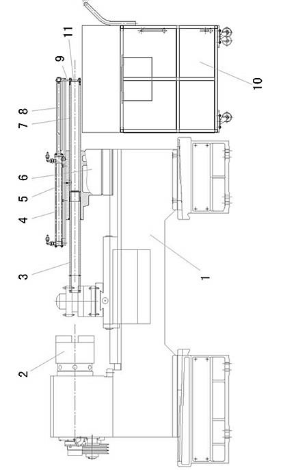
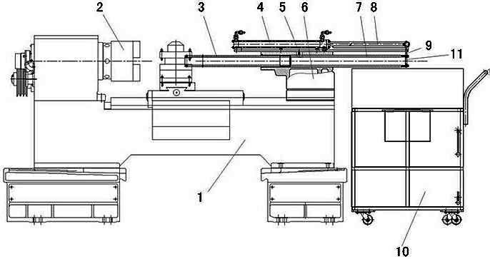
[0008] Such as figure 1 As shown: 1 is the bed of a programmable CNC lathe, a chuck 2 is installed on the upper left of the bed 1 through the headstock, and a tailstock 6 is arranged on the guide rail above the bed 1, between the tailstock 6 and the guide rail The structure is the same as the prior art. A tubular mandrel 7 is arranged in the tailstock 6, the right end of the tubular mandrel 7 stretches out to the rear side of the tailstock 6, and the center line of the tubular mandrel 7 is parallel to the guide rail longitudinally on the bed 1 top. A material receiving pipe 3 is connected to the left end of the tubular mandrel 7 through a threaded connection, and the left end of the material receiving pipe 3 stretches out to the front side of the tailstock 6 . The top of the tailstock 6 is fixedly connected with the oil cylinder 4 connected with the hydraulic control device, and the outer end of the piston rod 8 matched with the oil cylinder 4 is connected with the right end ...


PUM


Abstract

The invention relates to a programmable numerically-controlled machining lathe with an automatic blanking auxiliary machine. The programmable numerically-controlled machining lathe comprises a lathe body, wherein the left part above the lathe body is provided with a chuck through a main spindle box; a tailstock is arranged on a guide rail above the lathe body; a tubular central spindle is arranged in the tailstock; the central line of the tubular central spindle is parallel to the longitudinal direction of the guide rail above the lathe body; a material receiving pipe is connected to the left end head of the tubular central spindle; an oil cylinder which is connected with a hydraulic control device is fixedly connected to the upper side of the tailstock; the outer end head of a piston rod matched with the oil cylinder is connected with the right end head of the tubular central spindle through a connecting plate; and the central lines of the oil cylinder and the piston rod are parallel to the longitudinal direction of the guide rail above the lathe body. The programmable numerically-controlled machining lathe has the advantages of simple structure and action reliability and ensures that machined workpieces are orderly collected one by one, so that a phenomenon that the workpieces fly about everywhere is avoided, the safety degree of equipment and the machining efficiency are improved, and need of collecting the workpieces placed everywhere is avoided.

Description

technical field [0001] The invention relates to a lathe, in particular to a programmable numerical control lathe with an automatic blanking auxiliary machine. Background technique [0002] Existing programmable machining CNC lathes include a bed, a spindle box is arranged on the left side above the bed, and a chuck is installed through the main shaft in the headstock. A bed saddle that slides longitudinally along the guide rail is provided on the guide rail above the bed body, and a slide plate for installing a knife rest that slides laterally along the guide rail is provided on the bed saddle. When the lathe with this structure cuts off the workpiece after processing, the falling point of the workpiece is not clear, and the direction of the tangential force rotating with the chuck is uncertain. Sometimes it will fall directly on the bed surface, and sometimes it will fly far away, which is unsafe. It cannot be automatically concentrated in the same position, which will bri...

Claims


Application Information

Patent Timeline
IPC IPC(8): B23B15/00B23B7/00
Inventor 赵宏安王飞颜涛岳云萍王进付承云黄付中薛志红
Owner 大连机床(数控)股份有限公司
Learn More