
AC pulse arc welding control method

A technology of arc welding and control method, which is applied in the direction of arc welding equipment, welding equipment, manufacturing tools, etc., can solve the problems of arc disappearance, welding status instability, electrode reduction, etc., and achieve the purpose of suppressing arc disappearance, reducing sputtering, reducing The effect of small splashes

Active Publication Date: 2012-05-02
DAIHEN CORP
View PDF7 Cites 11 Cited by
  • Summary
  • Abstract
  • Description
  • Claims
  • Application Information

AI Technical Summary

Problems solved by technology

However, when the electrode positive polarity base current Ib is reduced, arc disappearance tends to occur, and the welding state tends to become unstable.

Method used


Image

  • AC pulse arc welding control method
  • AC pulse arc welding control method
  • AC pulse arc welding control method

Examples


Embodiment approach 1

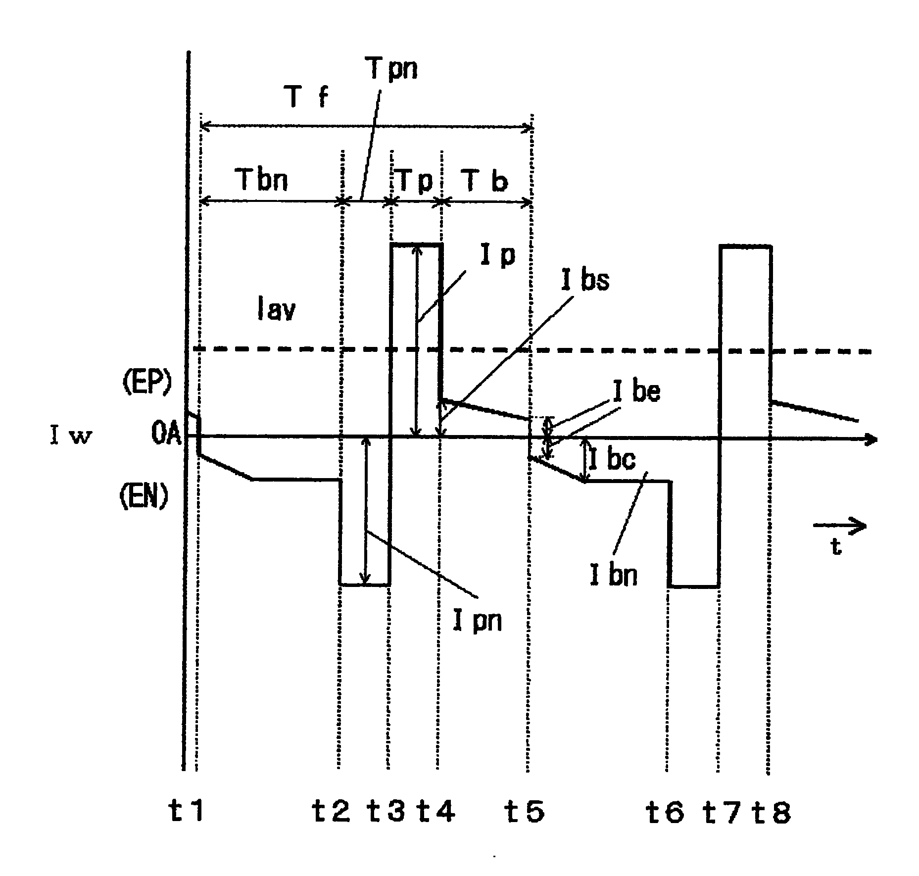
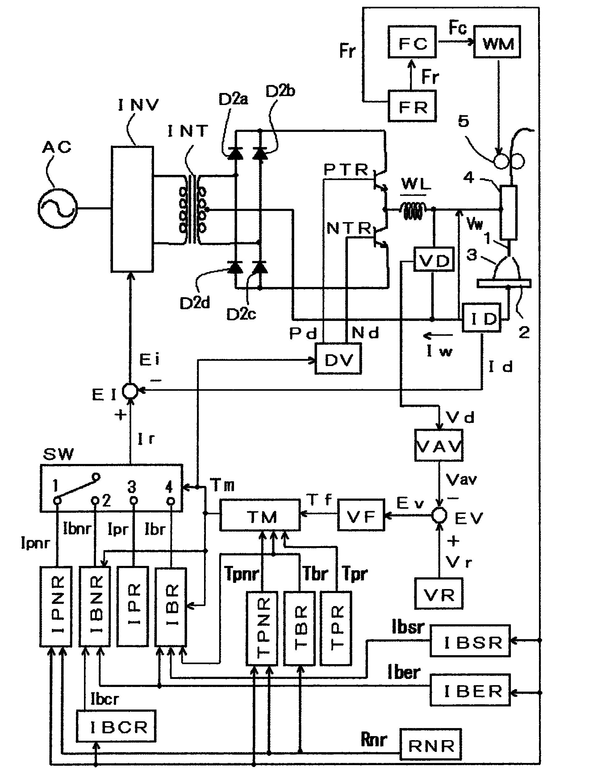
[0107] figure 1 It is a waveform diagram showing the welding current Iw of the AC pulse arc welding control method according to Embodiment 1 of the present invention. exist figure 1 In , starting from 0A, the upper side represents the positive polarity of the electrode EP, and the lower side represents the negative polarity of the electrode EN. figure 1 This indicates that the electrode negative polarity current ratio is set larger than the normal range (about 0 to 30%). exist figure 1 In this method, in order to prevent arc extinction at the time of polarity switching, a high voltage is applied between the welding wire and the base metal for a short period of time at the time of polarity switching. figure 1 with the above Figure 4 Correspondingly, and are the same except for the operation of the electrode positive polarity base period Tb and the electrode negative polarity base period Tbn, so the description thereof is omitted. Below, refer to figure 1 Be explained....


PUM

PropertyMeasurementUnit
diameteraaaaaaaaaa

Abstract

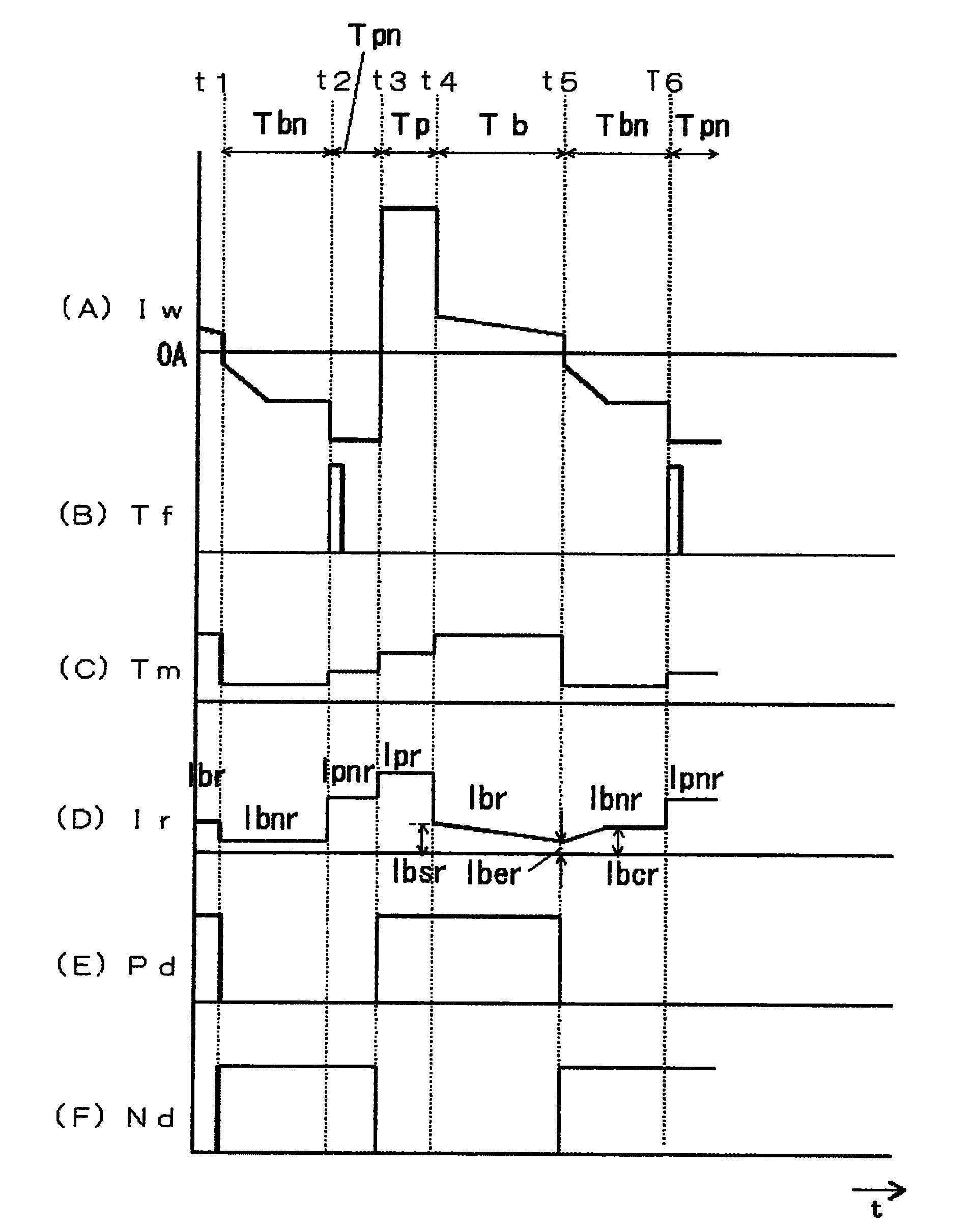
The invention provides an AC pulse arc welding control method, wherein during the negative electrode polarity-based period (Tbn), the negative electrode polarity-based current (Ibn) smaller than the critical value is electrified. During the negative electrode peak-based period (Tpn), the negative electrode peak-based current (Ipn) greater than the negative electrode polarity-based current is electrified. During the positive electrode peak-based period (Tp), the positive electrode peak-based current (Ip) greater than the critical value is electrified. During the positive electrode polarity-based period (Tb), the positive electrode polarity-based current (Ib) smaller than the critical value is electrified. Therefore, the welding can be performed. The positive electrode polarity-based current (Ib) is inclined to be smaller along the passing of time. The front half part of the positive electrode polarity-based current (Ib) is capable of increasing so as to inhibit the disappearing of electric arc. The rear half part of the positive electrode polarity-based current (Ib) is capable of decreasing so as to reduce the sputtering of electric arc.

Description

technical field [0001] The present invention relates to an AC pulse arc welding control method capable of obtaining a stable welding state when the electrode negative polarity current ratio is set to a large value. Background technique [0002] In general AC pulsed arc welding, while feeding the welding wire at a constant speed, the peak current and the base current during the positive polarity period of the electrode and the base current during the negative polarity period of the electrode are used as A cycle is repeated to carry out welding. In this AC pulse arc welding, the heat input to the base material can be adjusted by adjusting the electrode negative polarity period and changing the electrode negative polarity current ratio. Therefore, low heat input welding is possible, enabling high-quality thin-plate welding. In addition, by changing the electrode negative polarity current ratio, it is possible to make the shape of the bead (bead) such as the depth of penetrati...

Claims


Application Information

Patent Timeline
Patent Type & Authority Applications(China)
IPC IPC(8): B23K9/095
Inventor 盐崎秀男高桥宪人
Owner DAIHEN CORP
Learn More