Method for using modular steel hysteresis damper

A variable damper and modular technology, applied in the field of steel hysteresis variable dampers, can solve the problem of not maximizing the energy dissipation effect of the damper, and achieve the effect of easy assembly and installation.

Active Publication Date: 2012-05-02
北京赛福思创减震科技股份公司
View PDF3 Cites 9 Cited by
  • Summary
  • Abstract
  • Description
  • Claims
  • Application Information

AI Technical Summary

Problems solved by technology

[0004] The purpose of the present invention is to provide a method for using a modular steel hysteresis damper, so as to solve the problem

Method used


Image

  • Method for using modular steel hysteresis damper
  • Method for using modular steel hysteresis damper
  • Method for using modular steel hysteresis damper

Examples


specific Embodiment approach 1

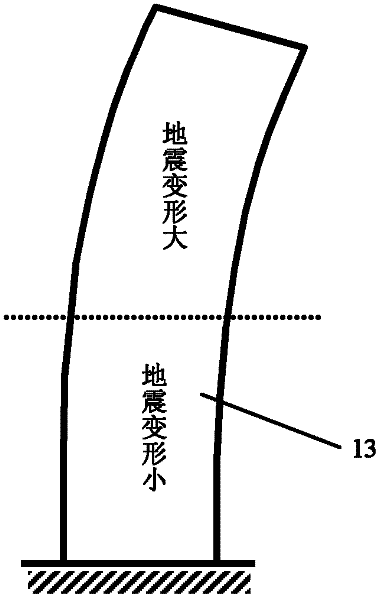
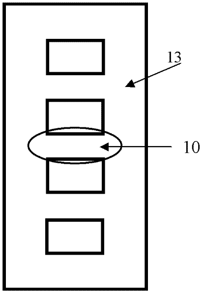
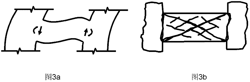
[0024] Specific implementation mode one: as Figure 1-20As shown, the modular steel hysteresis damper in the method of using the modular steel hysteresis damper described in this embodiment includes N energy dissipation layers 1, 2N+2 pressure plates 2, two pairs of splints 3 and two Anchor plate 8, N is a non-zero natural number; the cross section of each splint 3 is L-shaped, and each end between two adjacent energy dissipation layers 1 is provided with a pressure plate 2, and N energy dissipation layers 1 2N+2 pressure plates 2 are stacked alternately to form the main body of the damper. Two pressure plates 2 are respectively provided on the upper end surface and the lower end surface of the damper main body. And it is fixed on a pair of splints 3 through the connecting piece penetrating through the end, and the other end of the damper body with the pressure plate 2 is located between the other pair of splints 3 and is connected through the end through the connection The p...

specific Embodiment approach 2

[0031] Specific implementation mode two: as Figure 7-20 As shown, a plurality of ribs 9 are provided between two vertical surfaces of each splint 3 with an L-shaped cross section in the modular steel hysteresis damper described in this embodiment. Other components and connections are the same as those in the first embodiment.

specific Embodiment approach 3

[0032] Specific implementation mode three: as Figure 7-20 As shown, the number of N in the modular steel hysteresis damper described in this embodiment ranges from 10 to 40 pieces. Other components and connections are the same as those in the first embodiment.


PUM


Abstract

The invention discloses a method for using a modular steel hysteresis damper, which relates to the method for using the steel hysteresis damper and solves the problem that power consumption function of the damper is not showed completely due to the arrangement mode of the current shock absorption and power consumption damper. Mounting position of the modular steel hysteresis damper is determined; dampers are arranged on all the floors layer by layer up from the half height of a shear wall, and the planes on all the layers are ensured to be arranged symmetrically; an integral structure power model is built by using elastic-plastic analysis software, and specific quantity and type numbers of the modular steel hysteresis dampers arranged on each connecting beam are determined; yield shear force of the modular steel hysteresis damper arranged on a cutoff position of each connecting beam is between shear force in small seism and middle seism of the connecting beam; and, after the selected connecting beam is cut off from the middle part, space scale of the mounted modular steel hysteresis damper is matched with that of an cutoff opening of the connecting beam, thereby ensuring that the geometrical shape of the connecting beam is unchanged. The power consumption function of the damper is maximally showed due to the arrangement mode of the damper provided by the invention, so that the modular steel hysteresis damper is absolutely suitable for use in seismic design.

Description

technical field [0001] The invention relates to a method for using a steel hysteresis damper. Background technique [0002] The building structure shakes under the action of an earthquake. If the shaking is too large, the structure will be damaged or even collapsed, resulting in catastrophic consequences such as casualties and property losses. Dampers are energy consuming devices designed to dissipate this harmful energy that causes building structures to sway. According to the relationship between force and deformation, materials can be divided into elastic materials and plastic materials. The so-called elasticity refers to the corresponding deformation of the material after the force is applied, and the deformation disappears after the force is removed. For example, the rubber band is the representative of the elastic material; , a small increase in force produces a large deformation, and the deformation cannot completely disappear after the force is removed. This charac...

Claims


Application Information

Patent Timeline
IPC IPC(8): E04B1/98E04G21/14
Inventor 郭迅王涛郑志华
Owner 北京赛福思创减震科技股份公司
Why Eureka
Try Eureka