Down-the-hole oil pressure rotating device with oil distribution structure

A rotary device and hydraulic technology, applied in rotary drilling, rotary drilling rigs, drilling equipment and methods, etc., can solve the problems of large construction energy consumption and complicated pipeline layout.

Active Publication Date: 2013-11-06
MCC COMM CONSTR GRP CO LTD
View PDF5 Cites 0 Cited by
  • Summary
  • Abstract
  • Description
  • Claims
  • Application Information

AI Technical Summary

Problems solved by technology

[0006] The invention provides an in-hole hydraulic rotary device with an oil distribution structure, which solves the problem of complex pipeline layout of various construction media when the rotary device is used in conjunction with an air down-the-hole hammer or a hydraulic impactor in the prior art. The problem of high energy consumption in construction

Method used


Image

  • Down-the-hole oil pressure rotating device with oil distribution structure
  • Down-the-hole oil pressure rotating device with oil distribution structure

Examples


Embodiment Construction

[0021] The present invention will be further described in detail below in conjunction with the accompanying drawings and specific embodiments.

[0022] In the following description, some exemplary embodiments of the present invention are described by way of illustration only, and those of ordinary skill in the art will recognize that, without departing from the spirit and scope of the present invention, the The described embodiments can be modified in various ways. Accordingly, the drawings and description are merely illustrative in nature and are not intended to limit the scope of the claims. In addition, in this specification, the same reference numerals designate the same parts.

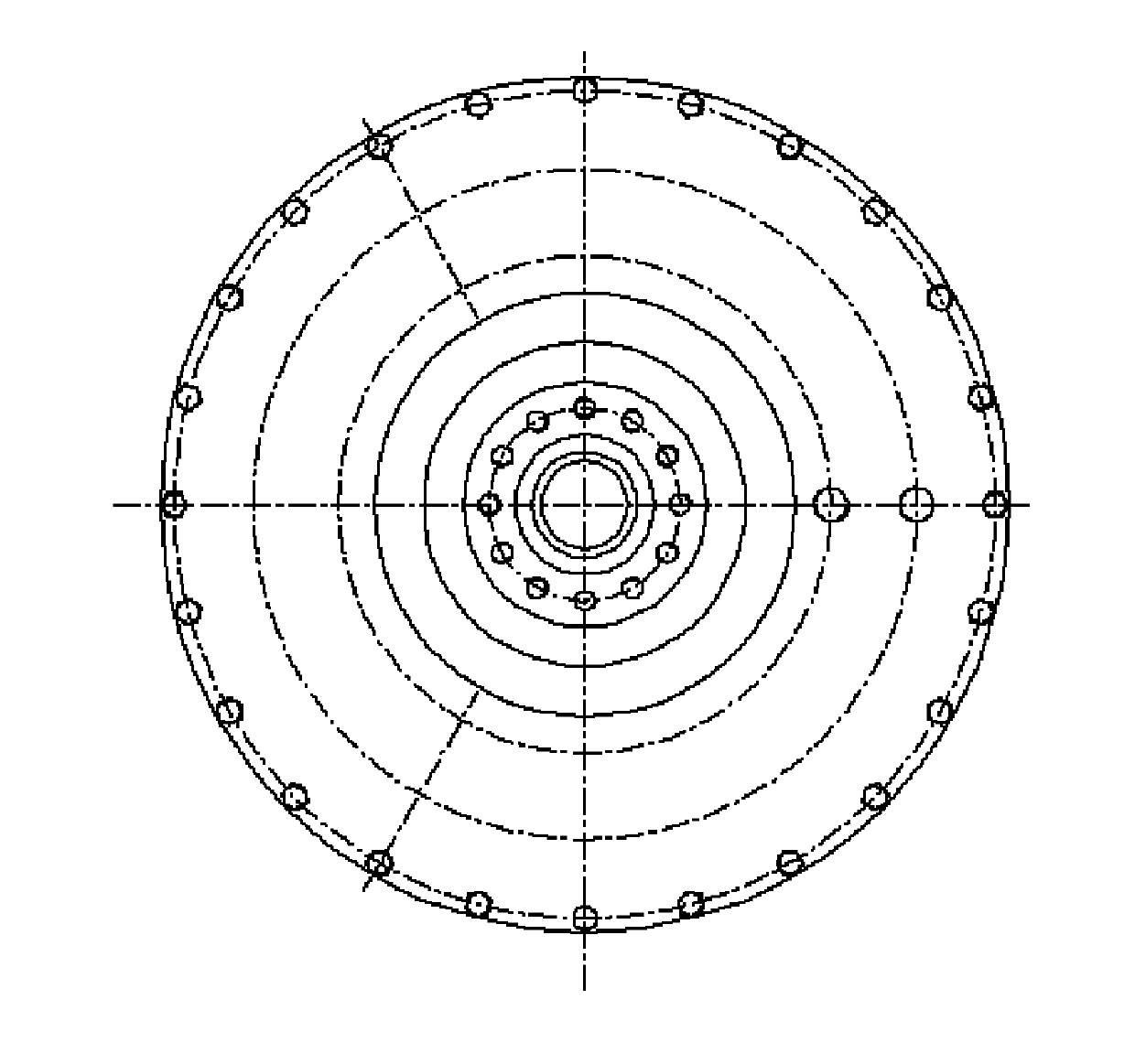
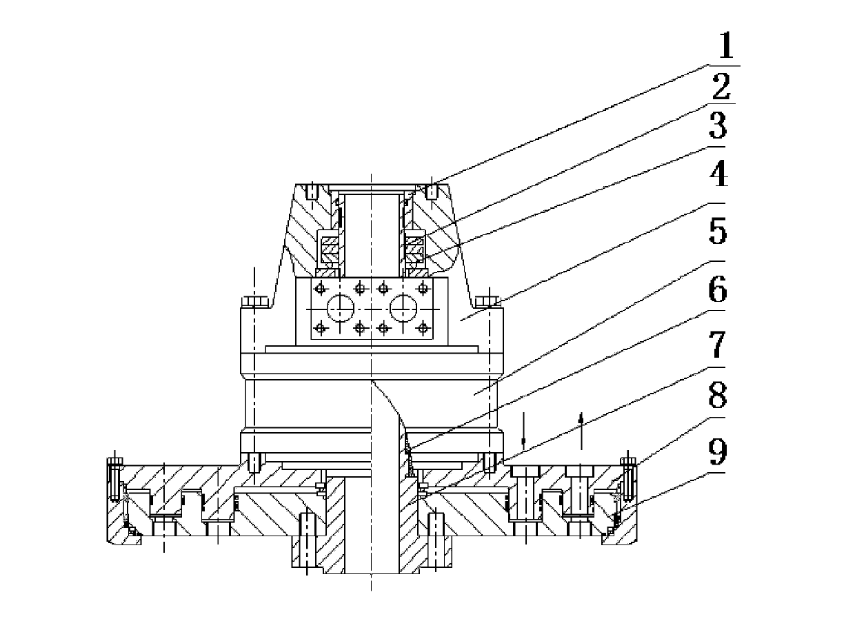
[0023] figure 1 It is a top view structure schematic diagram of the oil hydraulic rotary device in the hole with the oil distribution structure related to the present invention. figure 2 It is a schematic front view structure diagram of the in-hole hydraulic rotary device with oil distribution...


PUM


Abstract

The invention provides a down-the-hole oil pressure rotating device with an oil distribution structure. The down-the-hole oil pressure rotating device comprises a hollow mandrel which is provided with a thread at the upper end part, a through hole motor which is sleeved at a pre-set position of the hollow mandrel, a transition joint which is arranged on the upper end face of the through hole motor, a motor output shaft which is arranged at the lower end part of the through hole motor, a fixed disc of an oil distribution disc, a movable disc of the oil distribution disc, a spare fastening nut matching with the thread at the upper end part of the hollow mandrel, a thrust bearing which is arranged on the lower end face of the spare fastening nut and a sealing sleeve. According to the structure, the rotating device is arranged inside a hole when drilling so that the pipeline arrangement required in the construction which is realized by matching the rotating device with an air down-the-hole hammer or an oil pressure impactor is simple, thereby reducing energy consumption of the construction. Meanwhile, the down-the-hole oil pressure rotating device provided by the invention can prevent the influence on drilling, which is caused by that a water pipe is wound on a drilling rod due to incorrect use when a water tap cooperates with a drill in drilling. Furthermore, the drilling rod which is mounted at the upper part of the rotating device cannot be rotated so as to further reduce the energy consumption of the construction.

Description

technical field [0001] The invention relates to an in-hole hydraulic rotary device with an oil distribution structure. Background technique [0002] The slewing device is the main part of the drilling rig, which is mainly used to realize functions such as drilling and lifting. At present, when using a drilling rig to drill large-diameter bored piles in the prior art, the rotary device is usually fixedly installed on the ground surface, and the drill pipe is driven to rotate by rotating on the surface of the hole, and then the drill bit under the hole is driven to rotate. Drill the hole. However, in most cases, an air down-the-hole hammer or an oil pressure hammer is required to cooperate with a drilling rig to drill holes. When the drill pipe is rotated, the pipeline layout of various construction media is complicated, which brings many difficulties to drilling. At the same time, the rotation of the pipeline will increase the useless work, that is, increase the energy cons...

Claims


Application Information

Patent Timeline
Patent Type & Authority Patents(China)
IPC IPC(8): E21B3/02
Inventor 李国民肖剑殷学智刘峰
Owner MCC COMM CONSTR GRP CO LTD
Why Eureka
Try Eureka