
Electromagnet differential motion driving method for double-electromagnet proportional directional-flow valve

A proportional directional valve and differential drive technology, used in fluid pressure actuation devices, servo motor components, mechanical equipment, etc., can solve the problems of limited application scope and system control algorithm, slow response time of proportional valve, etc. Improve dynamic responsiveness, high driving force, and avoid impact effects

Inactive Publication Date: 2012-05-02
ZHEJIANG UNIV +1
View PDF4 Cites 3 Cited by
  • Summary
  • Abstract
  • Description
  • Claims
  • Application Information

AI Technical Summary

Problems solved by technology

[0008] In this control mode, due to the influence of electromagnet hysteresis and pure hysteresis, the proportional valve is slow in both response time and response speed, which limits its application range and the implementation of system control algorithms.

Method used


Image

  • Electromagnet differential motion driving method for double-electromagnet proportional directional-flow valve
  • Electromagnet differential motion driving method for double-electromagnet proportional directional-flow valve
  • Electromagnet differential motion driving method for double-electromagnet proportional directional-flow valve

Examples


Embodiment Construction

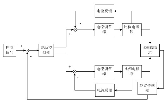
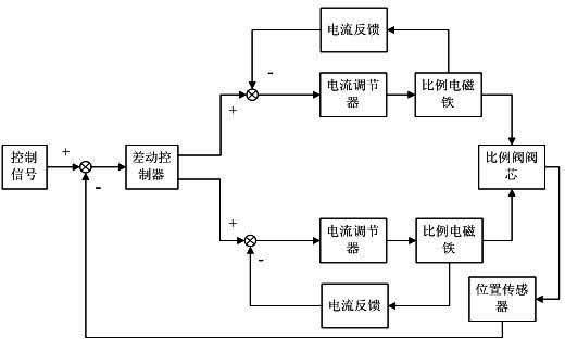
[0013] The present invention will be further described below in conjunction with the accompanying drawings and embodiments. like figure 1 As shown, the control signal is an analog signal or a digital signal, and the differential controller performs differential processing on the input signal as the control quantity driven by the current of the two electromagnets. Since the driving current of the electromagnet can only be a non-negative number, the unit It has no practical significance when the two outputs are negative numbers, which are obtained by the following formula:

[0014]

[0015]

[0016] in: , are the two outputs of the differential controller, , , is the steady-state operating point of the electromagnet, for the control signal.

[0017] The differential signal and current feedback are synthesized as the input of the current regulator to realize the current closed-loop control. The position sensor is used to detect the displacement of the proporti...


PUM


Abstract

The invention relates to an electromagnet differential motion driving method for a double-electromagnet proportional directional-flow valve. Under an existing control method, due to hysteresis loop and influence of pure lag of an electromagnet, a proportional valve is relatively slow whether in response time or in response speed so that implements in applied range and system control algorithm are limited. When controlling the proportional directional-flow valve for action, by processing control signals, the electromagnet differential motion driving method generates two paths of differential motion signals so as to drive proportional electromagnets at two ends of the proportional directional-flow valve at the same time, then the electromagnets at two ends can together act on a valve core. Compared with an electromagnet in a traditional control method, the differential motion driving method has larger driving force and throughout works within a proportional electromagnet linear area, thereby avoiding influence to dynamic property of the valve core caused by alternately switching on and off of the two electromagnets and improving dynamic response capability of the valve.

Description

technical field [0001] The invention relates to the field of hydraulic control, in particular to an electromagnet differential drive method for a double electromagnet proportional directional valve. Background technique [0002] The electro-hydraulic proportional control technology is based on the traditional hydraulic transmission technology characterized by open-loop transmission and the electro-hydraulic servo control technology characterized by closed-loop control, in order to meet the higher requirements of general engineering systems for transmission and control characteristics , a new branch with vigorous vitality in the field of fluid transmission and control that has gradually developed since the 1960s and 1970s. Today, electro-hydraulic proportional technology has become an indispensable means of industrial machinery, engineering construction machinery and cutting-edge national defense products, and has received special attention from relevant industrial and techni...

Claims


Application Information

Patent Timeline
IPC IPC(8): F15B13/02
Inventor 金波朱雅光张德盛陈飞飞顾振国陶键
Owner ZHEJIANG UNIV
Learn More