Vibration reduction structure of low-temperature scanning near-field optical microscope

A technology of scanning near-field optics and vibration-damping structures, applied in scanning probe microscopy, scanning probe technology, non-rotational vibration suppression, etc. And other issues

Inactive Publication Date: 2012-05-02
PEKING UNIV
View PDF5 Cites 12 Cited by
  • Summary
  • Abstract
  • Description
  • Claims
  • Application Information

AI Technical Summary

Problems solved by technology

Existing SNOM equipment generally works under normal room temperature conditions, and the vibration reduction part is generally not strictly designed, and even the scanning part of SNOM is simply placed on the optical vibration reduction platform, which cannot meet the requirements of low-temperature vacuum environment. Vibration Reduction Requirements for Scanning Near-Field Optical Microscopy

Method used


Image

  • Vibration reduction structure of low-temperature scanning near-field optical microscope
  • Vibration reduction structure of low-temperature scanning near-field optical microscope

Examples


Embodiment Construction

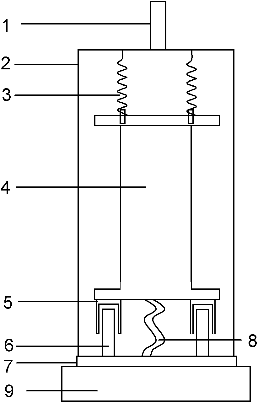
[0011] Referring to the accompanying drawings, the entire damping component is suspended on the lifting rod of the cryogenic cavity through a rigid hook 1 . The rigid hook 1 is connected to the center of the top of the metal sleeve 2 . The SNOM scanning head 4 is suspended on the top of the metal sleeve 2 by three springs 3 . Six copper frames 5 are fixed on the lower surface of the scanning head base, and the corresponding six square NdFeB magnets 6 fixed on the thermally conductive copper plate 7 are located in the middle of the copper frame, but do not contact the copper frame, forming a magnetic resistance Ni vibration damping device. When vibration occurs, on the one hand, the spring 3 damps the vibration, and on the other hand, the copper frame 5 moves along one side of the magnet 6 to cut the magnetic force line to cause magnetic damping, which plays the role of vibration reduction. The metal sleeve 2 is fixed to the bottom heat-conducting copper plate 7, so that the ...


PUM


Abstract

The invention discloses a vibration reduction structure of a low temperature scanning near-field optical microscope (SNOM), and belongs to the field of manufacture of near-field optical instruments. The vibration reduction structure is characterized in that a vacuum cavity of the low temperature scanning near-field optical microscope is internally provided with a metal sleeve, a low temperature SNOM scanning head is hung on the top in the metal sleeve so as to play the role of primary vibration reduction action; further a magnetic damping vibration reduction device is arranged on the vibration reduction structure, a U-shaped copper frame of the magnetic damping vibration reduction device is partially fixed on the lower surface of a scanning head pedestal, and a corresponding magnet is fixed on a heat conduction copper disc; when the vibration reduction structure is vibrated, one edge of the U-shaped copper frame does a motion of cutting the magnetic line of force along one edge of the magnet so as to cause magnetic damping, thereby playing a secondary vibration reduction action. The vibration reduction structure provided by the invention can be used for reducing of the low temperature scanning near-field optical microscope.

Description

technical field [0001] The invention belongs to the technical field of manufacturing near-field optical instruments, in particular to a vibration-reducing structure of a low-temperature scanning near-field optical microscope. Background technique [0002] Near-field optical microscopy (SNOM) exploits near-field interactions and can achieve a resolution of less than 100 nm, far superior to far-field microscopy limited by diffraction barriers. The idea of ​​using near-field optics for imaging was first proposed by Synge in 1928, who showed that the combination of illuminating an object through a subwavelength aperture and a detector very close to the sample allowed high resolution to be obtained through a non-diffraction-limited process. The conventional experimental instrument that turned the principle into reality was completed by Pohl et al. in 1984, so that the scanning near-field optical microscope was realized, and the optical diffraction limit was truly broken. Scannin...

Claims


Application Information

Patent Timeline
Patent Type & Authority Applications(China)
IPC IPC(8): F16F15/04F16F15/02G01Q60/18
Inventor 林峰赵华波朱星
Owner PEKING UNIV
Why Eureka
Try Eureka